
Electric bus chassis integration involves coordinating the bus body frame with the chassis structure, including mounting plate positions, connection methods, and clearance around suspension and steering components.
Using a 6.5 m battery-electric city bus as an example, this article examines a typical three-section chassis frame structure, the connection methods used between the body frame and chassis, and key areas to consider during body-to-chassis integration.
1. Electric Bus Chassis Integration and the Three-Section Frame Structure
The electric chassis in this example features a typical three-section frame structure. The front and rear overhang sections are fixed structures provided by the chassis manufacturer, while the central truss structure generally requires separate design to suit the body layout.
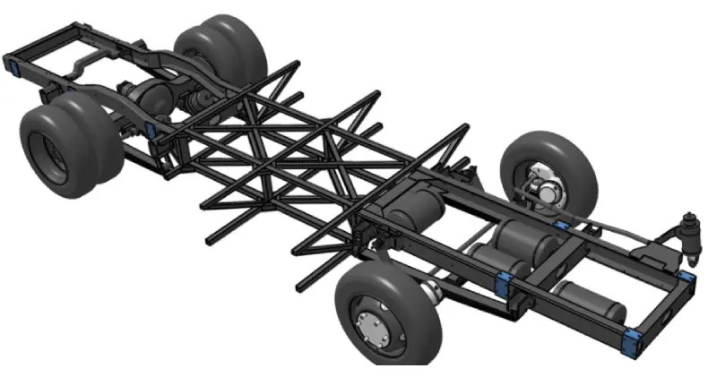
For this type of electric bus chassis integration, the body builder should coordinate with the chassis manufacturer in advance to confirm the mounting plate design and positions. These details affect how the body frame connects to the chassis.
2. Mounting Plates and Welded Brackets for Electric Bus Chassis Integration
Mounting Plates on the Chassis Rails
The mounting plate design and positions should be agreed upon with the chassis manufacturer before the body frame is assembled. The mounting plates are secured to the chassis longitudinal rails using rivets or bolts, with bolted connections being more common.
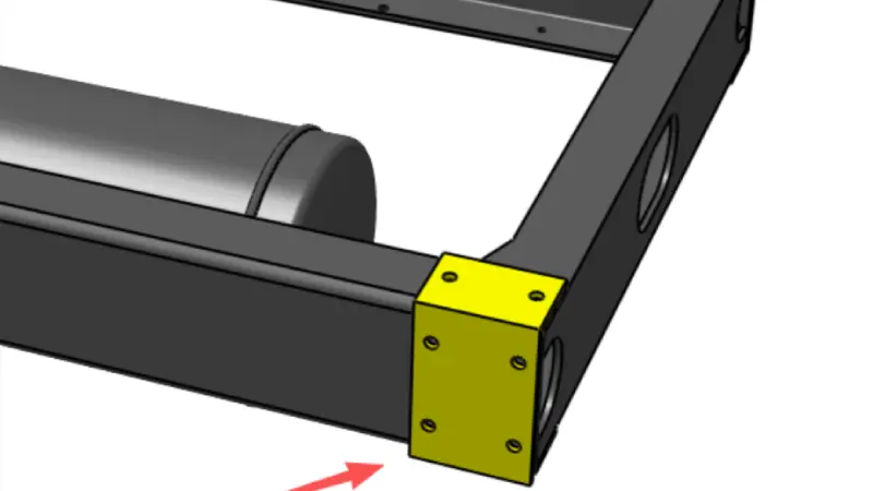
In this 6.5 m electric bus example, the typical mounting plate specifications are:
- Material: Q345 steel
- Thickness: At least 5 mm
These specifications describe the example shown and should not be interpreted as universal requirements for every electric bus chassis.
Welded Outrigger Brackets
Another connection detail shown in the reference illustration uses outrigger brackets welded to the chassis rails. The purple areas in the illustration indicate the weld seams.
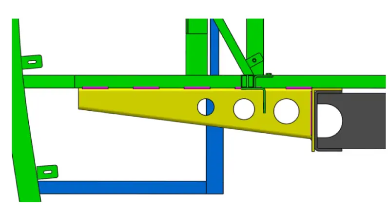
The brackets typically use the following specifications:
- Material: Q345 steel
- Thickness: 4 mm
The illustration shows how the mounting plate connects to the chassis rail through the outrigger bracket structure.
3. Body Frame Assembly and Chassis Fitting
Once the body frame has been assembled, it is lowered onto the chassis from above.
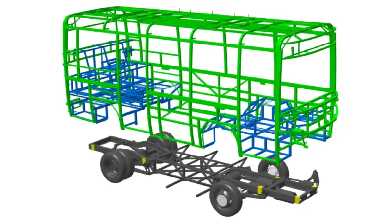
The mounting plate positions and connection arrangements should therefore be established during the design stage, based on the chassis structure and the planned body layout. This allows the body frame and chassis connection points to be coordinated before assembly.
4. Key Connection Areas in Electric Bus Chassis Integration
When integrating the body frame with an electric bus chassis, several areas require attention.
A-Pillar and Front Body Area
The connection points around the A-pillar and front body structure should be considered in relation to the chassis mounting arrangement.
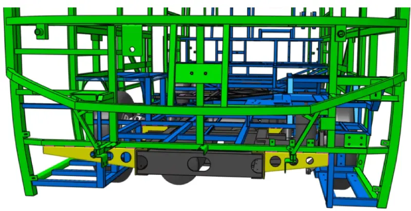
Front Suspension Area
Check the clearance between the body structure and the front suspension components. In particular, verify that the body structure does not interfere with upward leaf spring travel or the steering tie rod.
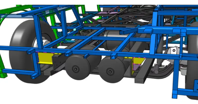
Central Frame Section
The central section generally requires design work to suit the body layout. As shown in this example, rectangular steel tubing with the same specification as the chassis crossmembers can be used for the connection.
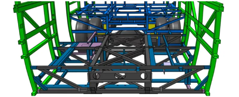
Rear Suspension Area
Check for potential interference between the body structure and the rear leaf springs during upward suspension travel.
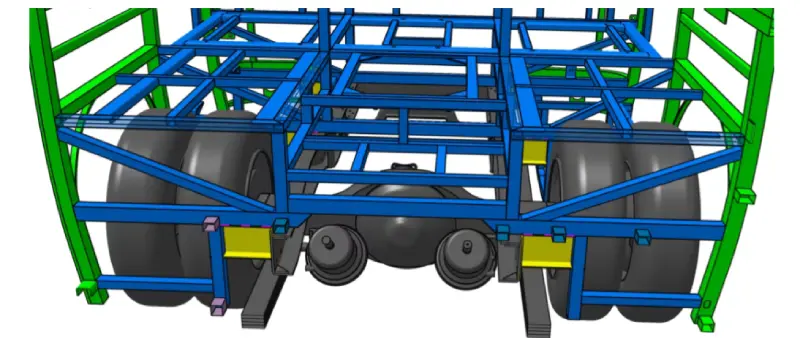
Rear Body Area
The connection points around the rear body structure should also be considered when planning the body-to-chassis mounting arrangement.
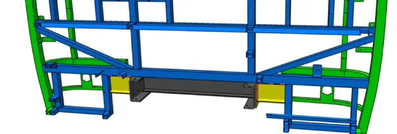
5. Key Considerations for Electric Bus Chassis Integration
This 6.5 m electric bus example illustrates several important aspects of electric bus chassis integration:
- Coordinate mounting plate positions early. Confirm the mounting plate design and locations with the chassis manufacturer before body assembly.
- Understand the three-section frame structure. The front and rear overhang sections are defined by the chassis manufacturer, while the central truss structure generally requires design work to suit the body layout.
- Check key connection areas. Pay particular attention to the front and rear suspension areas, steering tie rod clearance, and the connection points around the A-pillars and rear body.
The mounting methods and material specifications described here are based on this specific example. The final connection details will depend on the chassis structure and body design.
Jenwyn Tech Electric Bus Chassis and Complete Bus Solutions
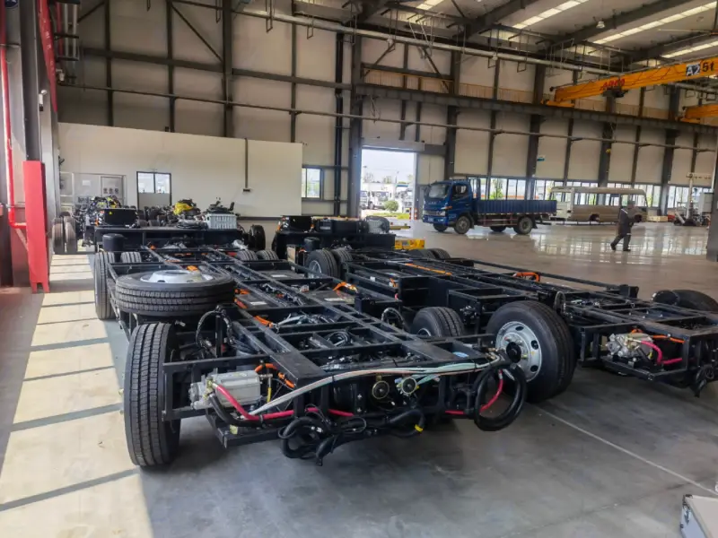
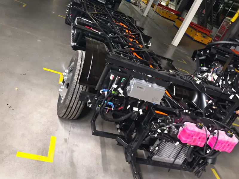
Jenwyn Tech provides electric bus chassis solutions for 6–9 m and 10–12 m buses, supporting urban transit, shuttle buses, and other commercial passenger vehicle applications. Our chassis platforms integrate key EV systems, including the electric powertrain, battery system, battery thermal management system, braking and suspension systems, HVAC, etc., with configurations adaptable to different body structures and vehicle requirements.
For bus manufacturers developing their own vehicle platforms, we support chassis configuration and body mounting interface design to meet specific integration requirements.
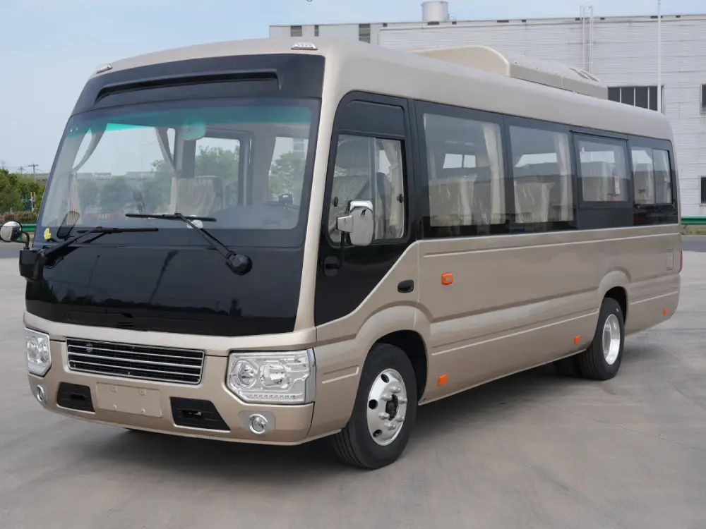
In addition to electric bus chassis, Jenwyn Tech can also supply complete electric buses to meet different customer and project requirements. Whether you need a chassis for your own body development or a complete electric bus, we offer flexible supply options to suit different business models and vehicle platform needs.
Explore our Electric Bus Chassis Solutions to learn more about our chassis platforms and configurations.
Get in touch with Jenwyn Tech to discuss your electric bus project and component requirements. You can contact our team at contact@jenwyntech.com or complete the form below.