
The electric vehicle control system coordinates the operation of electrical, powertrain, and vehicle subsystems. From interpreting driver inputs and managing energy flow to controlling high-voltage power-up sequences and monitoring system faults, it plays a central role in vehicle performance, safety, and operational efficiency.
This article examines the architecture of an electric vehicle control system, the functions of the Vehicle Control Unit (VCU), CAN bus communication, subsystem integration, high- and low-voltage power-up processes, and key vehicle control strategies.
Table of Contents
- Overview of the Electric Vehicle Control System
- Vehicle Control Unit (VCU)
- CAN Bus Communication Architecture
- Key Functions of the VCU
- VCU Interfaces and Component Connections
- Power Supply and Vehicle Power-Up Process
- Fault Diagnosis and Diagnostic Interfaces
- Electric Vehicle Control Strategies
- Conclusion
1. Overview of the Electric Vehicle Control System
1.1 Role and Functions of the Electric Vehicle Control System
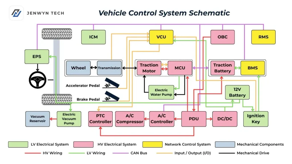
The vehicle control system serves as the central coordination platform of an electric vehicle. Its primary responsibilities include data exchange between subsystems, information processing, battery energy management, driver intention interpretation, safety monitoring, and fault diagnosis.
Its performance directly affects four key vehicle characteristics: driving performance, energy efficiency, safety, and driving comfort.
Unlike conventional internal combustion engine vehicles, electric vehicles use a traction battery, electric drive motor, and power electronics in place of the traditional engine and transmission system. As a result, vehicle control is no longer simply an extension of engine management. It has evolved into an integrated platform that coordinates high- and low-voltage electrical systems, vehicle network communications, and energy distribution.
1.2 Three Main Subsystems
The electric vehicle control system can be divided into three closely coordinated subsystems:
| Subsystem | Main Components | Primary Functions |
|---|---|---|
| Low-voltage electrical system | 12V battery, low-voltage wiring, ignition switch, relays, electric water pump, electric brake vacuum pump, electric power steering (EPS), instrument cluster (ICM) | Supplies power to electronic control units, high-voltage component controllers, and 12V auxiliary devices |
| High-voltage electrical system | Traction battery, drive motor, motor controller (MCU), onboard charger (OBC), DC/DC converter, electric A/C compressor, PTC heater | Converts electrical energy into mechanical energy and performs AC/DC rectification, inversion, and DC voltage conversion |
| Network control system | VCU, BMS, remote communication module (RMS), gateway, CAN bus | Coordinates the low- and high-voltage systems and manages communication across the vehicle |
Electronic control components are generally referred to as ECUs or ECMs, while controllers managing high-power electrical components are commonly called power controllers.
The underlying principle is to use low-current control signals to manage high-current electrical circuits, providing a controlled and reliable interface between vehicle control logic and high-power components.
2. Vehicle Control Unit (VCU)
2.1 Basic Functions of the VCU
The Vehicle Control Unit (VCU) is the central controller of the vehicle control system.
It receives information from the accelerator pedal, brake pedal, vehicle speed sensors, battery state of charge (SOC), and other vehicle systems. Based on these inputs, the VCU coordinates the operation of the components required to drive and operate the vehicle.
Its primary role is supervisory control and coordination across the vehicle.
The main hardware components of a VCU include:
- Microprocessor or MCU chip
- Power supply and protection circuits
- I/O interfaces and debugging modules
- Analog-to-digital (A/D) conversion modules
- CAN bus communication modules
Together, these components enable signal acquisition, logical processing, control output, and communication with other vehicle systems.
2.2 Four-Layer VCU Management Architecture
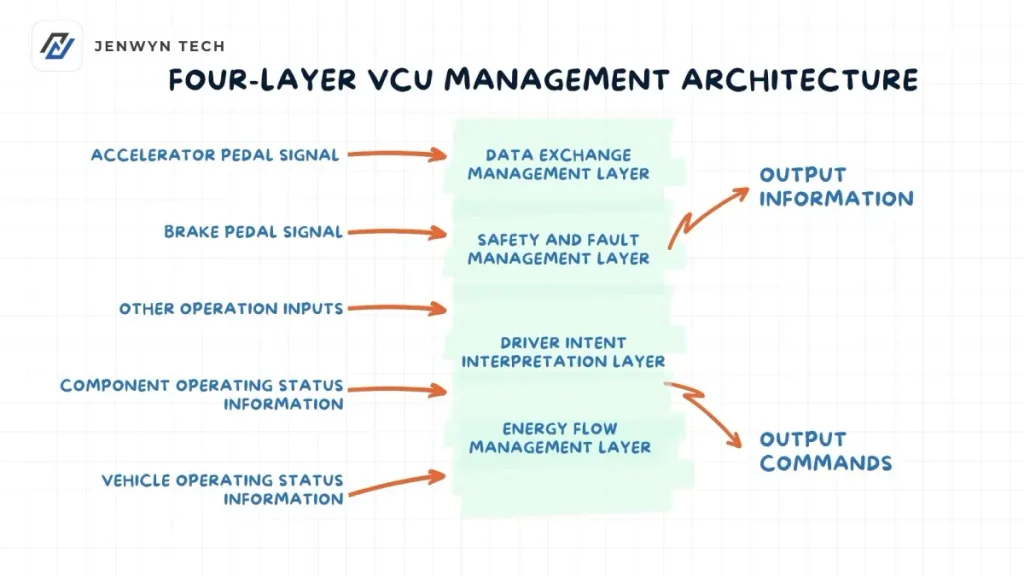
According to signal importance and functional execution sequence, VCU operations can be divided into four layers, from the bottom level to the top level:
| Layer | Name | Main Functions |
|---|---|---|
| Layer 1 | Data Exchange and Communication Management | Receives CAN bus messages, collects and processes physical signals, transmits control commands through CAN, and provides output signals to displays, relays, and other devices through I/O interfaces. This layer supports all other functions. |
| Layer 2 | Safety and Fault Management | Analyzes integrated vehicle data, identifies faults, and initiates appropriate responses. It defines the permissible operating range of components while maintaining vehicle safety and accommodating driver demands where possible. |
| Layer 3 | Driver Intention Interpretation | Processes driver inputs, including accelerator pedal, brake pedal, and gear position signals, to calculate target drive torque and required vehicle power. |
| Layer 4 | Energy Flow Management | Distributes power demand among available energy sources and coordinates energy storage devices, including the traction battery, supercapacitors (if equipped), and 12V battery. |
The design principle behind this architecture is straightforward: establish reliable communication and safety first, interpret driver inputs second, and optimize energy distribution afterward.
Higher-level functions depend on the proper operation of the lower-level functions.
2.3 Evolution of VCU Architecture
With increasing processor capabilities and the adoption of domain controller architectures, the configuration of vehicle control systems is evolving.
In earlier electric vehicle models, vehicle control functions were handled by an independent VCU.
In newer models, the independent VCU was eliminated. Vehicle control functions were redistributed between the motor controller (MCU) and battery management system (BMS).
This decentralized architecture can reduce system complexity and cost, but places higher computational demands on the MCU and BMS.
3. CAN Bus Network Architecture
The Controller Area Network (CAN) bus acts as the communication network connecting electronic control units throughout an electric vehicle.
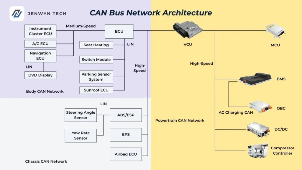
The number of CAN networks and the combination of connected controllers vary by vehicle design. A common configuration uses three CAN networks:
| Network | Transmission Speed | Main Coordinating Unit | Connected Components |
|---|---|---|---|
| Powertrain CAN | 500 kbit/s (high speed) | VCU/BMS | MCU, BMS, DC/DC converter, compressor controller; a separate slow-charging CAN connection may be used between the BMS and OBC |
| Chassis CAN | 500 kbit/s (high speed) | ABS/ESP | ABS/ESP, EPS, airbag ECU, steering angle sensor, and yaw rate sensor |
| Body CAN | 125 kbit/s (medium speed) | BCU/Navigation ECU | BCU, instrument cluster ECU, A/C BCU, navigation ECU; LIN connections for seat heating, switch modules, reversing sensors, and sunroof |
Powertrain CAN and chassis CAN generally use higher communication speeds because electric motor control and anti-lock braking require fast and reliable signal transmission. Communication delays must be controlled at the millisecond level.
Body CAN operates at a lower speed because systems such as air conditioning, power windows, and seat heating have less demanding real-time communication requirements.
In addition, the Body Control Unit (BCU) can act as a master control unit, connecting four slave modules through the LIN bus: the seat heating module, switch module, parking sensor module, and sunroof module.
The navigation ECU can also act as a master unit and communicate with the DVD display through LIN.
LIN is a lower-cost supplement to CAN and is suitable for applications that do not require high communication speeds.
4. Sixteen Core Functions of the VCU
VCU responsibilities vary depending on vehicle design and system architecture. However, its functions can generally be summarized into the following 16 categories:
| No. | Function | Description |
|---|---|---|
| 1 | Driver Intention Interpretation | Converts accelerator and brake pedal signals into drive motor torque commands according to predefined control logic, directly influencing driving response. |
| 2 | Gear Shift Control | Identifies valid gear positions, handles gear-related faults safely, and alerts the driver to incorrect operations through the instrument cluster. |
| 3 | Drive Control | Issues drive torque commands according to pedal inputs, gear position, vehicle speed, and road conditions to meet performance, safety, and comfort requirements. |
| 4 | Regenerative Braking Control | Recovers energy during coasting and braking in two stages without interfering with ABS operation. |
| 5 | Hill-Start and Rollback Prevention | Limits backward movement during hill starts to less than 10 cm and maintains vehicle speed at 0 km/h when available drive power is insufficient on an incline. |
| 6 | Charging Process Control | Works with the BMS to manage charging power and prevent the vehicle from being driven while connected to a charger. |
| 7 | Intelligent Charging and Battery Balancing | Automatically wakes the BMS to charge the 12V battery when its SOC falls below 73%, and stops charging when it exceeds 93%. Cell balancing is also performed after AC charging. |
| 8 | High-Voltage Power-Up and Shutdown Control | Controls the switching sequence of the main negative, pre-charge, and main positive relays. |
| 9 | Vehicle Energy Management | Coordinates high-voltage systems, including the battery, motor, DC/DC converter, compressor, and PTC heater, with low-voltage systems such as EPS, vacuum pump, A/C, and BCM. |
| 10 | Electric Auxiliary System Management | Monitors the operating status of the high-voltage compressor, 12V EPS, and 12V brake vacuum pump. |
| 11 | Real-Time Vehicle Status Monitoring and Display | Monitors subsystem conditions through sensors and CAN communication and displays relevant information through the instrument cluster. |
| 12 | Fault Diagnosis and Handling | Classifies faults into three levels: critical faults trigger immediate high-voltage shutdown; urgent faults lead to power limitation or standby mode; warning faults are reported and recorded. |
| 13 | CAN Network Management | Manages information organization and transmission, network nodes, dynamic communication priorities, and network status monitoring. |
| 14 | Online Calibration Through CCP | Monitors ECU variables, adjusts control parameters online, and saves calibration data. |
| 15 | Remote Status Monitoring | Allows users to check vehicle information, such as battery SOC and estimated driving range, through a mobile application. |
| 16 | Remote Vehicle Control | Supports remote charging control, air conditioning operation, and battery preheating through a mobile application. |
4.1 Two-Stage Regenerative Braking Control
Regenerative braking is one of the key characteristics that distinguishes electric vehicles from conventional vehicles.
Based on accelerator and brake pedal positions, the VCU divides energy recovery into two stages.
Stage 1: Coasting Energy Recovery
When the driver completely releases the accelerator pedal without pressing the brake pedal, the VCU commands the drive motor to operate as a generator.
The motor produces reverse torque, creating a deceleration effect while converting kinetic energy into electrical energy for battery charging.
Stage 2: Braking Energy Recovery
When the driver presses the brake pedal to slow down, the VCU adds regenerative braking torque to the mechanical braking system to recover energy.
If the driver releases the accelerator and immediately presses the brake pedal, the system enters the second stage directly.
4.2 Hill-Start and Rollback Prevention
During a hill start, there is a short control gap between releasing the brake pedal and pressing the accelerator pedal. Without sufficient holding torque, the vehicle may roll backward.
The rollback prevention function uses precise motor torque control to bridge this gap.
Hill-start rollback prevention:
The system aims to limit backward movement to less than 10 cm.
When the brake pedal is released, the VCU immediately sends a torque-holding command to the MCU. Once accelerator pedal input is detected, the system smoothly transitions from holding torque to drive torque.
Rollback prevention while climbing:
If insufficient drive power causes vehicle speed to gradually decrease to 0 km/h on an incline, the VCU commands the motor to generate holding torque to maintain the vehicle at a standstill and prevent backward movement.
5. VCU Connections with Other Vehicle Components
5.1 VCU and Electronic Gear Selector
For example, an EV model uses a rotary electronic gear selector with four positions:
- R: Reverse
- N: Neutral
- D: Drive
- E: Economy
The electronic gear selector sends four signal lines to the VCU using four-bit binary encoding.
| Gear Position | Signal 1 | Signal 2 | Signal 3 | Signal 4 |
|---|---|---|---|---|
| R (Reverse) | 1 | 1 | 0 | 0 |
| N (Neutral) | 1 | 0 | 0 | 1 |
| D (Drive) | 0 | 1 | 0 | 1 |
| E (Economy) | 0 | 1 | 1 | 0 |
The voltage thresholds are defined as follows:
- 0.1–0.9 V: Logic 0
- 2.8–3.95 V: Logic 1
Four-bit encoding provides additional fault tolerance and safety compared with simpler two- or three-bit encoding. The VCU can identify invalid signal combinations and reject the corresponding commands.
The E position activates Economy mode. It reduces energy consumption by adjusting acceleration response sensitivity and limiting maximum vehicle speed.
In both D and E modes, the driver can use the E+ and E- buttons to select among three levels of regenerative braking intensity.
5.2 VCU and Accelerator Pedal Sensor
The accelerator pedal sensor sends two independent signals to the VCU. The VCU compares both signals to perform redundancy checks.
| Parameter | Signal 1 | Signal 2 |
|---|---|---|
| Angular Range | 0.2°–14.5° (corresponding to 0%–100% pedal travel) | 0.2°–14.5° (corresponding to 0%–100% pedal travel) |
| Voltage Range | 0.7–4.8 V | 0.37–2.4 V |
| Signal Relationship | Primary signal, increasing linearly | Verification signal, approximately half the voltage of Signal 1 |
The key feature of this dual-signal design is that the voltage range of Signal 2 is approximately half that of Signal 1.
The VCU continuously compares the two signals. If the deviation exceeds the permitted range, the system identifies a sensor fault and enters a safety mode, such as limp-home mode.
This is a typical application of functional safety principles in vehicle control systems.
5.3 VCU and Brake Pedal Sensor
The brake pedal sensor also sends two redundant brake pedal position signals to the VCU.
The VCU compares these signals to determine braking demand and manage regenerative braking and braking force distribution.
It also sends a signal to activate the brake lights.
As with the accelerator pedal, the dual-signal design improves the reliability of driver input detection.
5.4 VCU and Battery Management System (BMS)
The VCU communicates with the BMS through both hardwired signals and the CAN bus.
It sends wake-up and main negative relay closing signals to the BMS through hardwired connections. It also uses CAN communication to check whether the BMS has any communication or signal reception faults.
The BMS provides the VCU with key battery information, including:
- Battery state of charge (SOC)
- Battery temperature
- Battery voltage
- Battery current
5.5 VCU and Onboard Charger (OBC)
When an AC charging connector is plugged into the vehicle, the OBC detects the connection between the CC and PE terminals and sends a charging wake-up signal to the VCU.
The VCU then sends a charging wake-up signal to the instrument cluster.
At the same time, the OBC sends a charging connection confirmation signal to the VCU, activating the AC charging indicator on the instrument panel.
5.6 VCU and PTC Heater Controller
The PTC heater controller can be integrated into the high-voltage distribution box, installed within the compressor controller, or configured as an independent unit.
The VCU communicates with the PTC controller through the CAN bus.
Based on driver settings and temperature sensor signals, the VCU controls the switching of different PTC heating stages to regulate cabin temperature.
5.7 VCU and Motor Controller (MCU)
The VCU sends torque demand commands to the MCU through the CAN bus and checks whether the MCU has encountered any command reception faults.
The MCU provides feedback information, including:
- Drive motor speed
- Drive motor temperature
- Motor controller temperature
During regenerative braking, the VCU sends corresponding control commands to the MCU. According to the control description in this architecture, the six IGBTs stop switching and the three-phase bridge operates in a rectification mode, converting mechanical energy into electrical energy for battery charging.
If the regenerative charging current exceeds the maximum charging current permitted by the traction battery, the MCU limits IGBT operation accordingly.
5.8 VCU and DC/DC Converter
During AC charging or vehicle operation, the VCU sends an Enable signal to the relevant relay.
Once the relay closes, the DC/DC converter begins operating, converting high-voltage DC power (approximately 300–400 V) into 14 V DC power.
This supplies the 12V battery and powers low-voltage electrical devices.
If the DC/DC converter develops a fault, it sends a fault signal to the VCU. The VCU then forwards the information to the instrument cluster, where the corresponding charging or electrical system warning light is activated.
5.9 VCU and Compressor Controller
In some vehicle architectures, the VCU also performs certain air conditioning control functions.
When the driver operates the A/C control panel, the VCU receives signals such as:
- A/C switch status
- Temperature settings
- Blower fan speed
- Evaporator temperature
- Cabin temperature
- Refrigerant line pressure
The VCU then transmits control commands to the compressor controller through the CAN bus, allowing the compressor to operate at different speeds according to cooling demand.
5.10 VCU and Remote Communication Module (RMS)
The RMS, also known as the telematics control unit or T-Box, connects to the VCU through the CAN bus.
Its main functions include:
- Receiving VCU commands and collecting vehicle operating information.
- Providing GPS and BeiDou positioning.
- Storing vehicle data locally on an SD card.
- Transmitting data wirelessly to a remote service platform.
- Retaining recent operating data as a vehicle data recorder or “black box”.
- Storing data when the network is unavailable and uploading it automatically once the connection is restored.
- Reporting GPS faults.
- Supporting remote software updates.
5.11 VCU and Remote Mode Switch
Some higher-specification vehicle models are equipped with a remote mode button.
When activated, the remote mode indicator illuminates, allowing users to perform selected vehicle functions through a mobile application, including:
- Remote charging control
- Remote air conditioning control
- Remote battery preheating
6. Low-Voltage and High-Voltage Power-Up Processes
6.1 Power-Up Characteristics of Electric Vehicles
Conventional internal combustion engine vehicles generally use a single 12V electrical supply system, making their power-up process relatively straightforward.
Electric vehicles have two electrical power systems: the 12V low-voltage battery and the high-voltage traction battery.
Consequently, vehicle activation involves two separate but interconnected stages: low-voltage power-up and high-voltage power-up.
The core principle is that the VCU coordinates the control units and manages the sequence of low-voltage control signals to connect or disconnect the traction battery relays.
This ensures that the vehicle completes power-up and shutdown correctly while maintaining communication and fault monitoring throughout the process.
6.2 Four Low-Voltage Power Supply Methods
| Power Supply Type | Alternative Name | Description |
|---|---|---|
| Permanent 12V Supply | Terminal 30 | Continuously supplies power from the 12V battery to components such as the OBC, ignition relays, motor relays, reverse light relay, A/C relay, BMS, DC/DC converter, RMS, ICM, and VCU. |
| ACC Supply | Accessory Circuit | Supplies auxiliary electrical equipment, such as the cigarette lighter and audio system, when the ignition switch is in the ACC position. |
| IG Supply | Terminal 15 | Supplies power to the ignition relay coil, electronic gear selector, regenerative braking switch, and instrument cluster when the ignition switch is in the ON position. |
| Wake-Up Power Supply | — | A relay closes after receiving a wake-up signal, allowing the corresponding control unit to transition from standby to active operation. |
6.3 Six Wake-Up Modes and Their Priority
The vehicle control system supports several wake-up modes depending on charging, driving, and remote operation requirements.
| Priority | Wake-Up Mode | Trigger Condition and Wake-Up Sequence |
|---|---|---|
| 1 (Highest) | DC Fast-Charging Wake-Up | DC charging connector inserted → charging station sends a 12V wake-up signal → VCU and RMS activated → power supply switches to the vehicle’s 12V battery → BMS, DC/DC, and ICM activated. |
| 2 | Remote AC Charging Wake-Up | Mobile app sends a wake-up command through the 4G network → RMS activated → RMS wakes the VCU → VCU activates BMS, DC/DC, and ICM. |
| 3 | AC Charging Wake-Up | AC charging connector inserted → OBC sends a wake-up signal → VCU and RMS activated → BMS, DC/DC, and ICM activated. |
| 4 | Driving Mode (ON Position) | Ignition switch turned to ON → IG contact closes → ignition relay coil energized → relay contacts close and send a wake-up signal → VCU, RMS, and EPS activated → VCU subsequently activates motor relay, BMS, and DC/DC. |
| 5 | Remote Driving Mode | Mobile app wakes RMS → RMS wakes VCU → VCU activates the relevant control units. |
| 6 (Lowest) | DC/DC Conversion Mode | 12V battery SOC falls below 73% → IBS network wakes VCU and DC/DC → automatic charging stops when SOC reaches 93% (applicable to selected models such as EX3). |
The priority sequence follows the principle of charging safety first, followed by remote control, normal driving, and battery maintenance.
DC fast charging involves high-voltage operation and high current, which explains its highest wake-up priority in this architecture.
6.4 High-Voltage Power-Up Process
6.4.1 Functions of the Pre-Charge Relay and Resistor
If the motor controller is connected directly to the full traction battery voltage, typically 300–400 V, a sudden inrush current can place considerable stress on the high-voltage capacitors inside the controller.
This may damage power electronic components such as IGBTs.
The pre-charge resistor limits the initial current by charging the controller’s capacitors before the main relays close.
Once the capacitor voltage approaches the battery voltage, the main relay can close, completing the high-voltage circuit through a controlled soft-start process.
6.4.2 High-Voltage Relay Switching Sequence
The typical sequence described in this architecture is:
- The VCU commands the main negative relay to close.
- The BMS commands the pre-charge relay to close, initiating pre-charging.
- The system checks whether pre-charging is complete by comparing capacitor voltage with battery voltage.
- The BMS commands the main positive relay to close.
- The pre-charge relay opens, leaving the main high-voltage circuit fully connected.
This process is referred to as pre-charge and main positive relay sequencing.
The timing of each step must be carefully controlled, generally at the millisecond level.
During pre-charging, the BMS monitors current and capacitor voltage to determine whether the process is proceeding correctly.
If the pre-charge process exceeds the permitted time or abnormal current is detected, the BMS terminates the power-up sequence and reports a fault.
6.4.3 Normal Power-Up and Fault Shutdown
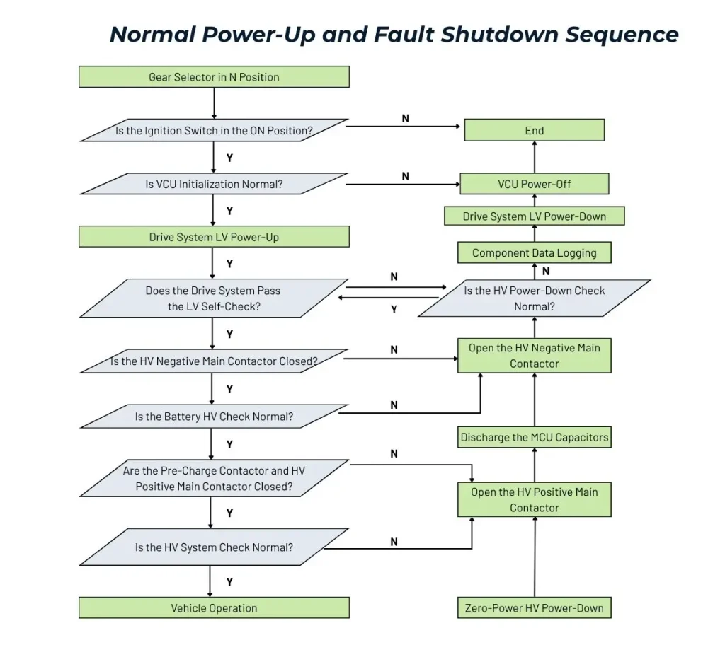
When the electronic gear selector is in Neutral (N) and the ignition switch is turned to ON, the vehicle first completes low-voltage power-up.
If the system self-check is successful, the high-voltage power-up process begins.
Once high-voltage activation is completed successfully, the green READY indicator illuminates on the instrument cluster, indicating that the vehicle is ready to drive.
If a fault is detected during high-voltage activation, such as low insulation resistance, abnormal battery temperature, or a pre-charge timeout, the system automatically initiates shutdown.
The shutdown sequence is:
Main positive relay opens → pre-charge relay opens → main negative relay opens.
The corresponding warning indicators are also displayed on the instrument cluster.
When the ignition switch is moved from ON to ACC, a complete shutdown sequence is initiated if high-voltage output power is zero and the vehicle is stationary.
In some vehicle designs, high-voltage activation checks are triggered only when the ignition switch is moved to START. The READY indicator illuminates once the high-voltage system passes its checks.
7. Vehicle Fault Diagnosis System
7.1 Three-Level Fault Classification
The VCU continuously monitors the vehicle’s electronic control system.
Based on sensor inputs and CAN bus information from the drive motor, traction battery, onboard charger, and other components, it identifies faults, classifies their severity, activates warning indicators, and stores diagnostic trouble codes (DTCs).
Faults are divided into three levels:
| Level | Fault Category | Examples | Response |
|---|---|---|---|
| Level 1 | Critical Fault | Excessive traction battery temperature, excessively low insulation resistance | Immediate high-voltage shutdown; the vehicle may enter a limited operating state or stop completely, depending on the fault. |
| Level 2 | Urgent Fault | Low insulation resistance, abnormal temperature distribution | Power limitation, standby mode, prohibition of high-voltage activation, or charging inhibition. |
| Level 3 | Warning Fault | Low battery voltage, excessive charging current | Fault reporting, recording, and driver notification without immediate intervention. |
The fundamental principle of fault handling is:
Personal safety > Vehicle safety > Driving experience.
Level 1 faults trigger immediate high-voltage disconnection, even if this results in the vehicle stopping on the road.
Level 2 faults restrict power or certain vehicle functions while potentially allowing continued operation.
Level 3 faults are recorded and reported without directly affecting normal driving.
7.2 Powertrain Warning and Indicator Lights
| No. | Indicator | Description |
|---|---|---|
| 1 | READY | Vehicle activation completed; vehicle is ready to drive. |
| 2 | Powertrain Anti-Theft | The electronic code in the key chip does not match the vehicle registration ID. |
| 3 | Low Traction Battery SOC | Battery SOC has fallen below the specified threshold; charging is required. |
| 4 | Charging Cable Connected | Charging connector is inserted and the vehicle is in charging mode. |
| 5 | Charging Reminder / Charging in Progress | AC or DC charging is underway. |
| 6 | High-Voltage Disconnected | High-voltage system is disconnected and the vehicle cannot be driven. |
| 7 | Traction Battery Fault | A fault has been detected in the battery system and requires inspection. |
| 8 | Regenerative Braking Level | Displays the selected regenerative braking level (1–3). |
| 9 | Regenerative Braking Disabled | Regenerative braking is switched off. |
| 10 | Drive Power Limitation | Motor output power is restricted due to a fault or temperature condition. |
| 11 | System Fault | A fault has been detected in the vehicle control system. |
| 12 | Motor Overtemperature | Drive motor temperature exceeds the specified safety threshold. |
| 13 | Motor Fault | A fault has been detected in the drive motor system. |
| 14 | 12V Battery Fault | Abnormal low-voltage battery condition or insufficient battery charge. |
8. In-Depth Analysis of Vehicle Control Strategies
8.1 Power-Up Sequence Control
Power-up sequencing is one of the most critical strategies in vehicle control.
From turning the ignition switch to ON until the READY indicator illuminates, the VCU coordinates more than ten control units through a defined sequence of self-checks, communication handshakes, and pre-charging operations.
A failure at any stage may interrupt the power-up process.
Key design considerations include:
- Relay switching intervals: Each relay must close at the appropriate time, with a defined interval between switching operations, typically 50–200 ms, to ensure that the previous step has been completed.
- Pre-charge current monitoring: The BMS must continuously monitor current during pre-charging and terminate the process if the current exceeds the specified threshold.
- CAN communication checks: After the control units become active, CAN communication handshakes must be completed to confirm that the vehicle network is operating correctly.
8.2 Driver Intention Interpretation
Driver intention interpretation is one of the most complex VCU functions.
The VCU must process multiple input signals simultaneously, including:
- Two redundant accelerator pedal signals
- Two redundant brake pedal signals
- Four encoded gear position signals
- Vehicle speed signals
Based on these inputs, the VCU calculates the driver’s actual demand within milliseconds.
Key algorithms include:
- Pedal mapping curves: Convert pedal travel into torque demand through a defined, potentially nonlinear mapping relationship.
- Pedal rate-of-change detection: Identify rapid or gradual acceleration inputs.
- Brake-to-acceleration transition management: Coordinates the transition between braking and acceleration and supports rollback prevention.
- Gear position plausibility checks: Prevent invalid gear selection, such as accidentally selecting Reverse while driving.
8.3 Regenerative Braking Control Strategy
Regenerative braking control directly influences driving range and vehicle driving characteristics.
Excessive regenerative braking can cause strong deceleration when the driver releases the accelerator, potentially reducing passenger comfort.
Insufficient regenerative braking, on the other hand, reduces the amount of recoverable energy and may affect driving range.
The VCU dynamically adjusts regenerative braking torque according to parameters such as:
- Vehicle speed
- Battery SOC
- Brake pedal position
- ABS operating status
In ECO mode (E position), the system applies stronger regenerative braking, smoother acceleration response, and a lower maximum vehicle speed to improve energy efficiency.
In D mode, driving comfort and responsiveness receive greater priority, with moderate regenerative braking intensity.
The driver can also use the E+ and E- buttons to manually select among three regenerative braking levels.
8.4 Charging Management Strategy
The VCU and BMS work together to manage the complete charging process:
Charging connector inserted → Communication wake-up → Charging handshake → Parameter negotiation → Constant-current charging → Constant-voltage charging → Charging completed → Connector disconnected.
Throughout charging, the VCU monitors battery temperature. If the temperature exceeds the specified safety threshold, the system reduces charging power or terminates charging.
The Intelligent Battery System (IBS) provides an additional battery maintenance function.
While the vehicle is parked, it automatically monitors the 12V battery SOC. When SOC falls below 73%, it wakes the BMS to initiate charging. Charging stops automatically once SOC reaches 93%.
This function helps prevent the 12V battery from becoming discharged during extended vehicle parking, which could otherwise prevent the vehicle from starting.
9. Conclusion
The vehicle control system is one of the fundamental technologies that distinguishes electric vehicles from conventional internal combustion engine vehicles.
Its role extends well beyond connecting individual electrical components. It coordinates the operation of the powertrain, battery, charging system, chassis, and auxiliary systems, while managing driver inputs, energy distribution, and vehicle safety.
A well-designed VCU and vehicle control architecture provides the foundation for reliable powertrain integration, coordinated subsystem operation, and consistent vehicle performance.
Understanding how these systems communicate and interact is essential when developing and integrating electric vehicle platforms.
Get in touch with us
Jenwyn Tech provides commercial EV powertrain systems and chassis solutions for buses, trucks, light commercial vehicles, and off-highway applications. Our portfolio covers traction motors, electric axles, power electronics, batteries, thermal management systems, and electric auxiliary systems.
We work with OEMs, electric vehicle manufacturers, engineering partners, and system integrators to supply mature and reliable EV systems for different vehicle platforms and operating requirements.
Looking for an EV powertrain solution for your project? You can get in touch with our team at contact@jenwyntech.com or fill in the form below.