
Introduction
The transition from internal combustion engines to electric powertrains is also changing the way steering systems are designed in light commercial vehicles.
Early electric light trucks often retained steering architectures derived from conventional ICE vehicles. One common approach was to replace the engine-driven hydraulic pump with an electrically driven pump while keeping the hydraulic steering gear. This led to the wider use of Electro-Hydraulic Power Steering (EHPS).
As vehicle architectures became more electronically controlled, Electric Power Steering (EPS) provided another option by replacing the hydraulic assist system with an electric motor and electronic control system. Looking further ahead, Steer-by-Wire (SBW) can remove the direct mechanical connection between the steering wheel and road wheels.
Each architecture has different requirements for steering load, packaging, control, energy consumption and vehicle functions. This article reviews the basic architecture and control logic of EHPS and EPS, and discusses the potential role of SBW in future electric light trucks.
1. EHPS: Electric Pump with Hydraulic Steering Assist
EHPS combines a conventional hydraulic steering mechanism with an electrically driven pump.
Instead of using an engine-driven pump, the system uses an electric motor to drive the hydraulic pump. The steering gear and hydraulic circuit can therefore retain a relatively familiar architecture while the pump operation becomes independent of engine speed.
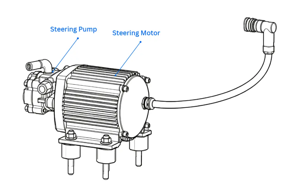
1.1 System Architecture
A typical EHPS system includes:
- Hydraulic steering gear
- Electric motor-pump unit
- Hydraulic reservoir
- Hydraulic lines
- Steering control unit
- Vehicle-speed and steering-related signals
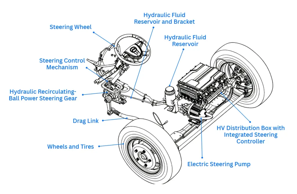
For light commercial vehicles using a recirculating-ball steering gear, the hydraulic actuator provides the steering assist required to move the steering linkage.
1.2 How EHPS Works
An EHPS system provides steering assistance through the combined operation of the electric steering pump and the hydraulic recirculating-ball steering gear. The electric steering pump generates the hydraulic pressure and flow required by the steering gear, while the steering gear converts the hydraulic pressure into mechanical steering assistance.
1.2.1 Operating Principle of the Hydraulic Recirculating-Ball Steering Gear
The hydraulic recirculating-ball steering gear uses a rotary valve to control the direction of hydraulic fluid flow between the two sides of the power piston.
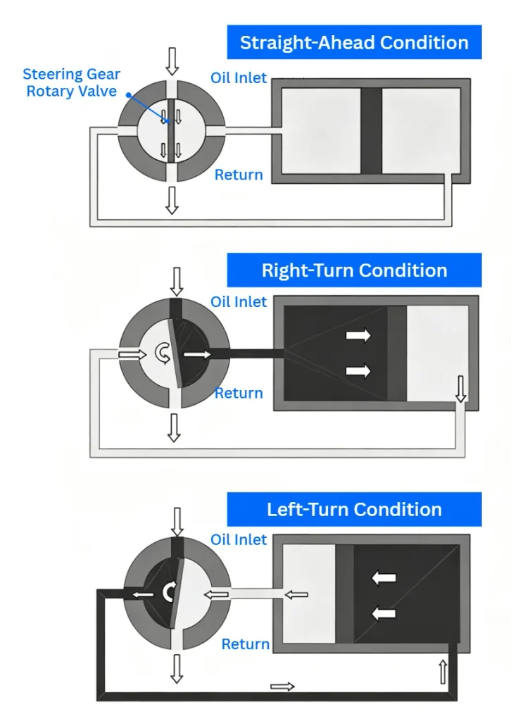
When the vehicle is traveling straight ahead and the driver is not applying steering input, the rotary valve remains in its neutral position. Hydraulic pressure in the front and rear chambers of the steering gear remains balanced, and the hydraulic circuit operates in an unloaded or bypass condition. The piston therefore remains essentially stationary, and the steering gear provides little or no hydraulic assistance.
When the driver turns the steering wheel, the steering input causes relative rotation between the input and output components of the steering gear, which moves the rotary valve away from its neutral position. The valve changes the opening of the pressure and return passages, directing high-pressure hydraulic fluid into one chamber of the steering gear while allowing fluid from the opposite chamber to return to the reservoir.
The resulting pressure difference across the piston generates hydraulic assist force and moves the piston in the corresponding direction. The piston movement is transmitted through the steering gear mechanism to the drag link and front wheels, reducing the steering effort required from the driver.
The direction of hydraulic assistance depends on the direction of steering input. During a right turn, the rotary valve directs pressurized hydraulic fluid to one side of the piston while the opposite chamber is connected to the return circuit. During a left turn, the hydraulic flow path is reversed, causing the piston to move in the opposite direction.
When the driver stops applying steering input, the rotary valve returns toward its neutral position. The pressure difference across the piston decreases, hydraulic assistance is reduced, and the steering gear returns toward its neutral operating condition.
Figure 3. Operating principle of a hydraulic recirculating-ball steering gear
1.2.2 Operating Principle of the Electric Steering Pump
The electric steering pump supplies the hydraulic flow and pressure required by the steering gear. It consists primarily of an electric steering motor and a hydraulic pump.
The vehicle’s high-voltage DC power is converted into three-phase AC power through the steering controller and inverter. The electric motor then drives the hydraulic pump, which circulates hydraulic fluid through the steering circuit.
Unlike a conventional engine-driven hydraulic pump, the electric steering pump can be controlled independently of engine speed. Its operating speed can therefore be adjusted according to vehicle speed, steering input, and required hydraulic flow.
1.2.3 EHPS Control Logic
The control strategy of the electric steering pump directly affects steering effort, steering feel, energy consumption, and hydraulic system durability.
During stationary steering and low-speed tight turns, the steering system requires relatively high hydraulic flow to provide sufficient steering assistance. At higher vehicle speeds and under smaller steering inputs, the required hydraulic flow can be reduced.
Variable-frequency control can therefore be used to adjust pump speed according to vehicle speed and steering angle. Higher pump speeds can be commanded during low-speed, large-angle steering maneuvers, while lower speeds can be used when steering demand is lower.
For example, the control logic can divide vehicle speed into several operating stages and steering input into different angle ranges. The controller then selects an appropriate pump speed for each combination of vehicle speed and steering angle.
The specific control parameters should be calibrated according to the vehicle platform, steering gear characteristics, front-axle load, vehicle mass, steering requirements, and hydraulic system specifications.
1.3 Fixed-Speed vs. Variable-Speed Pump Control
A fixed-speed pump is relatively simple, but it may continue operating at a high speed even when hydraulic demand is low.
A variable-speed EHPS can adjust pump speed according to operating conditions.
A typical control strategy may consider:
- Vehicle speed
- Steering angle
- Steering torque
- Pump speed
- Hydraulic pressure or flow demand
For example, a control map can increase pump speed during low-speed steering or large steering inputs, while reducing pump speed during higher-speed straight-line driving.
Example Variable-Speed Control Strategy
| Vehicle Speed | Steering Angle | Pump Speed |
|---|---|---|
| 0–30 km/h | 0° to ±10° | 1/2 nmax |
| 0–30 km/h | > ±10° | nmax |
| 30–60 km/h | 0° to ±10° | 1/2 nmax |
| 30–60 km/h | > ±10° | 3/4 nmax |
| 60–90 km/h | 0° to ±10° | 1/2 nmax |
| 60–90 km/h | > ±10° | 2/3 nmax |
| >90 km/h | All angles | 1/2 nmax |
The values above illustrate a possible control strategy. Actual pump-speed maps require calibration according to the vehicle, steering gear, front-axle load, hydraulic requirements and operating conditions.
1.4 EHPS Advantages and Limitations
| Advantages | Considerations |
|---|---|
| Familiar hydraulic steering architecture | Hydraulic components remain in the system |
| High assist capability | Pump and hydraulic circuit require packaging space |
| Electric pump is independent of engine speed | Hydraulic fluid and lines require maintenance |
| Suitable for commercial vehicle steering loads | Pump control affects auxiliary energy consumption |
| Can be integrated into existing vehicle architectures | Electronic control capability is more limited than EPS |
EHPS remains relevant where hydraulic steering assist and an established steering architecture are required.
2. EPS: Electric Assist with Electronic Control
Electric Power Steering (EPS) replaces the hydraulic assist system with an electric motor and electronic control.
For electric light trucks, an EPS system can use an electric recirculating-ball steering gear when the vehicle requires the load capability associated with this type of steering mechanism.
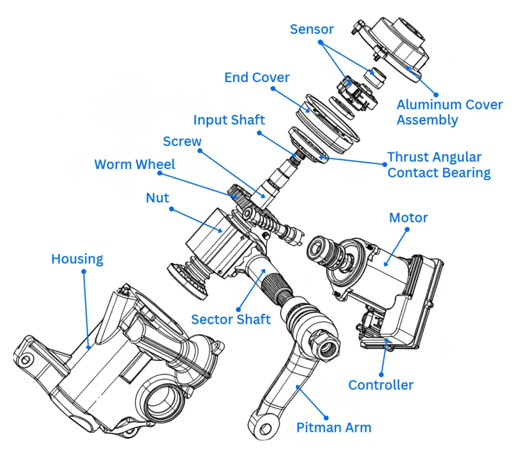
2.1 System Architecture
A typical electric steering system includes:
- Steering wheel and steering column
- Torque and angle sensor
- EPS control unit
- Electric steering motor
- Reduction mechanism
- Recirculating-ball steering mechanism
- Steering linkage
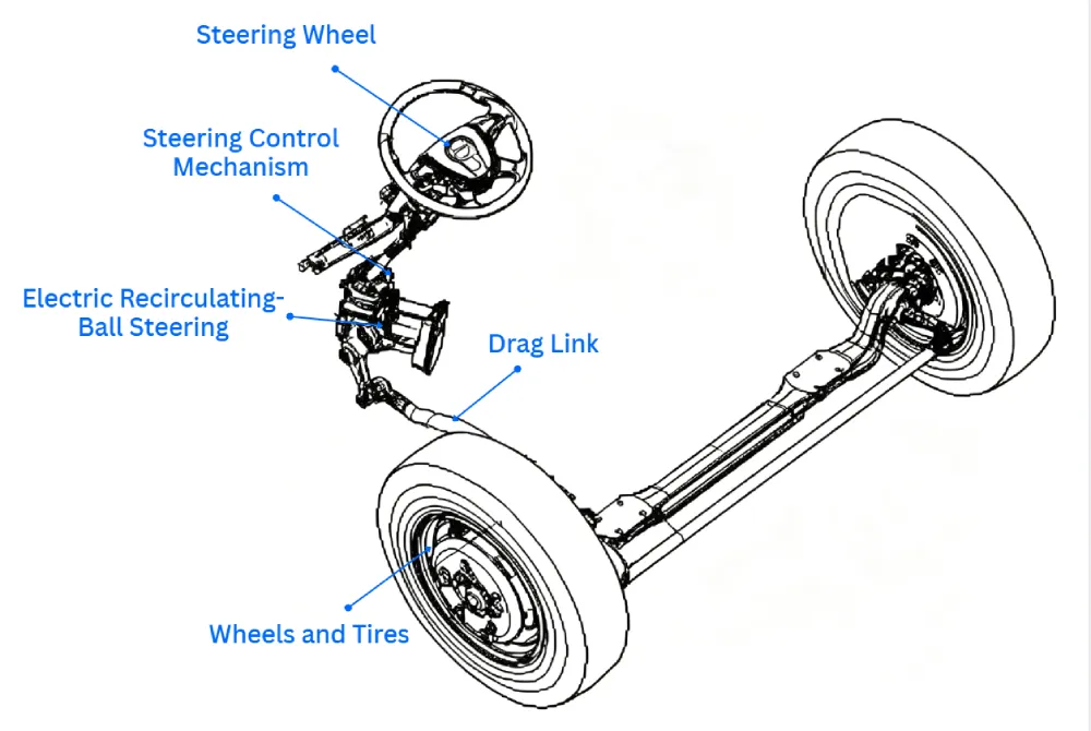
The sensor detects driver steering input. The controller then calculates the required assist torque and commands the motor accordingly.
2.2 How EPS Works
The torsion bar is an elastic element that connects the input shaft and output shaft. When the driver turns the steering wheel, the steering input rotates the input shaft and causes the torsion bar to deform.
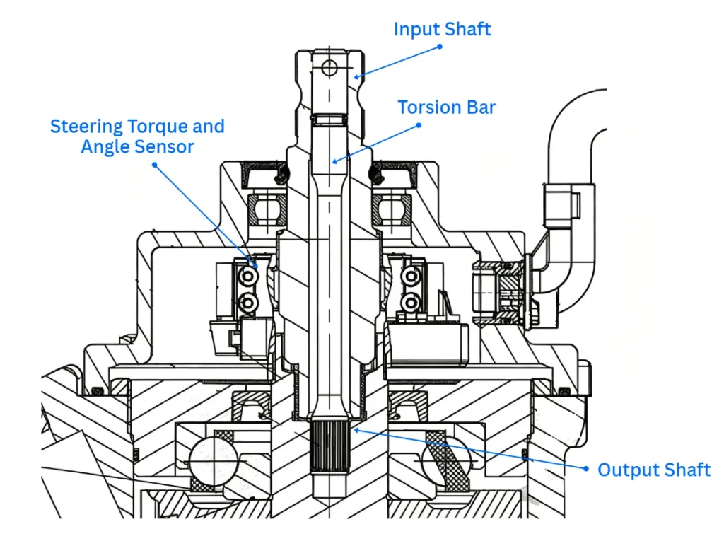
The steering torque and angle sensor detects the magnitude and direction of the steering-wheel torque based on the deformation of the torsion bar and the direction of rotation. It then converts these signals into electrical signals and sends them to the motor controller.
The motor controller processes these signals together with the vehicle speed signal to determine the motor rotation direction and the required assist current.
The electric motor drives the worm and worm-wheel reduction mechanism to amplify the motor torque. The amplified torque acts together with the driver’s steering input on the screw, causing the screw to rotate and drive the nut axially.
The nut engages with the rack mechanism, which drives the sector shaft to rotate. The sector shaft then moves the pitman arm back and forth, ultimately transmitting the steering input to the vehicle’s steering linkage.
2.3 Key EPS Control Functions
Variable Assist
Assist torque can be adjusted according to vehicle speed. Higher assistance can be provided during low-speed manoeuvring, while steering resistance can be increased at higher speeds.
Active Return
The motor can provide additional torque to support steering returnability after a steering input.
Damping Compensation
Electronic control can be used to modify steering response and suppress unwanted oscillation or vibration.
Friction Compensation
The controller can compensate for part of the mechanical friction within the steering system to improve steering feel.
ADAS Integration
Because steering assist is electronically controlled, EPS can provide a suitable actuation interface for functions such as Lane Keeping Assist and other driver-assistance features, subject to the vehicle’s overall architecture and safety design.
2.4 EPS Advantages and Limitations
| Advantages | Considerations |
|---|---|
| No hydraulic pump or hydraulic circuit | Motor torque capability limits the available steering assist |
| On-demand electrical operation | Higher steering loads may require a different architecture |
| Flexible software-based control | Requires electronic control and sensor systems |
| Adjustable steering characteristics | Functional safety and control validation are important |
| Easier integration with electronic vehicle functions | System cost and complexity depend on the architecture |
For electric light trucks, EPS provides a higher level of electronic control while eliminating the hydraulic components used in EHPS.
3. Steer-by-Wire: Toward Software-Defined Steering
Steer-by-Wire (SBW) takes electronic steering control further by removing the direct mechanical connection between the steering wheel and road wheels.
The steering system can be divided into two main functions:
- Steering input: Detects steering wheel position and driver input.
- Steering actuation: Uses an electric actuator to control the road wheels.
A road-wheel actuator and a separate steering-wheel feedback system can generate steering movement and steering feel electronically.
3.1 Potential Benefits of SBW
Removing the mechanical steering connection creates greater flexibility in steering control.
Potential benefits include:
- Variable steering ratio
- Software-defined steering feel
- Flexible steering-wheel positioning
- Reduced transmission of road shock and vibration
- Greater freedom in vehicle packaging
- Integration with automated driving functions
The steering ratio can also be adjusted according to vehicle speed and operating conditions. Faster steering response can be used during low-speed manoeuvring, while a slower response can provide a more stable steering feel at higher speeds.
3.2 Key Challenges
SBW also introduces additional system requirements.
The absence of a direct mechanical connection places greater importance on:
- Redundant sensors and actuators
- Fault detection and fault handling
- Functional safety
- Power supply redundancy
- System-level validation
The specific safety requirements depend on the vehicle architecture, safety goals and system design.
For commercial vehicles, cost, reliability, environmental durability and long-term field performance also need to be considered alongside the benefits of electronic steering control.
4. EHPS vs. EPS vs. SBW
| Item | EHPS | EPS | SBW |
|---|---|---|---|
| Steering assist | Hydraulic | Electric | Electric actuator |
| Mechanical steering connection | Yes | Yes | No direct mechanical connection |
| Hydraulic circuit | Yes | No | No |
| Pump required | Yes | No | No |
| Electronic control flexibility | Moderate | High | Very high |
| Active steering functions | Limited | Available | Extensive potential |
| ADAS integration | More limited | Available | High potential |
| System complexity | Moderate | Moderate–High | High |
| Typical consideration | Hydraulic assist and established architecture | Electronic control and packaging | Advanced vehicle architectures and automation |
The three architectures should not be viewed simply as successive replacements. The appropriate steering system depends on steering load, vehicle architecture, packaging, control requirements, cost and the functions required by the vehicle.
5. Conclusion
Electric light trucks are creating new requirements for steering systems as mechanical architectures become increasingly integrated with electronic control.
EHPS remains a practical architecture for vehicles that require hydraulic steering assistance, particularly where an established steering mechanism and high assist capability are important.
EPS removes the hydraulic system and provides greater control flexibility, making it suitable for electric vehicles where electronic steering functions and ADAS integration are becoming more important.
SBW represents a further architectural shift. By separating steering input from road-wheel actuation, it creates new possibilities for steering control, packaging and vehicle automation, while also introducing higher requirements for redundancy, functional safety and system validation.
The development of commercial EV steering systems is therefore not simply a move from one technology to another. EHPS, EPS and SBW each address different vehicle requirements, and system selection needs to be based on the vehicle’s steering load, architecture, operating conditions and control functions.
Jenwyn Tech EHPS & EPS for Electric Commercial Vehicles
Jenwyn Tech supplies electro-hydraulic power steering (EHPS) systems and EPS solutions for commercial EVs.
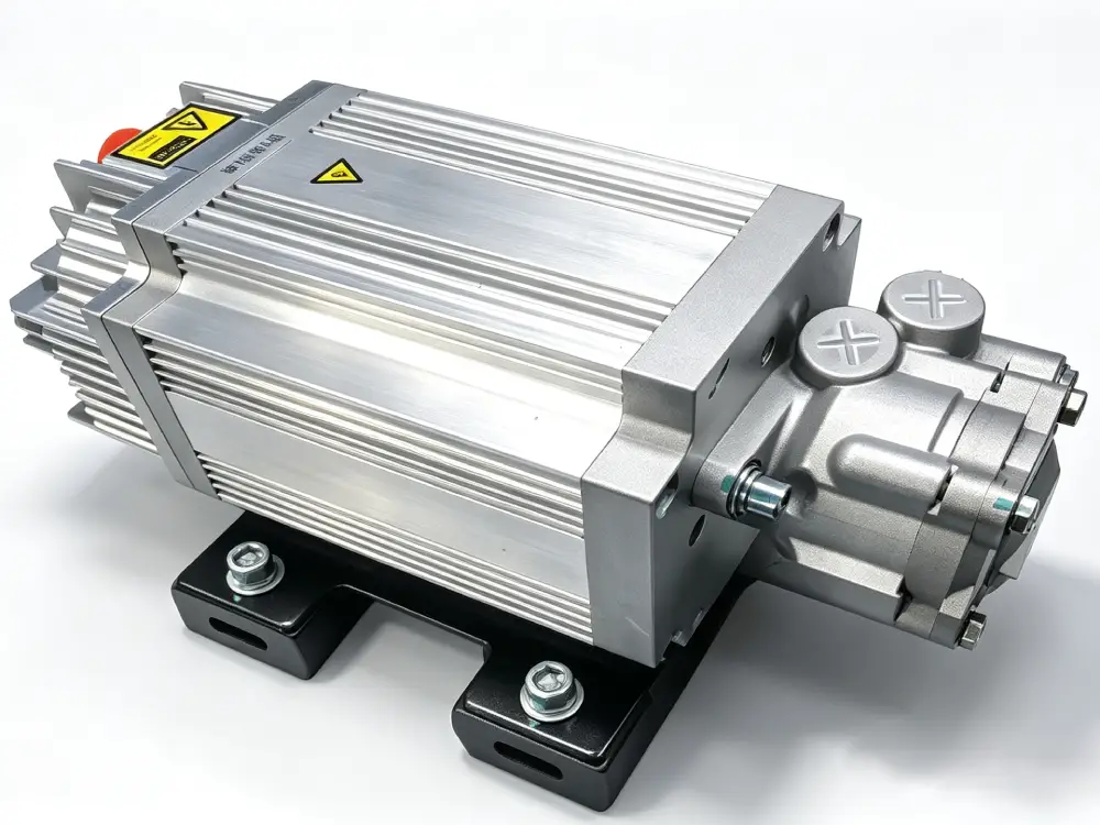
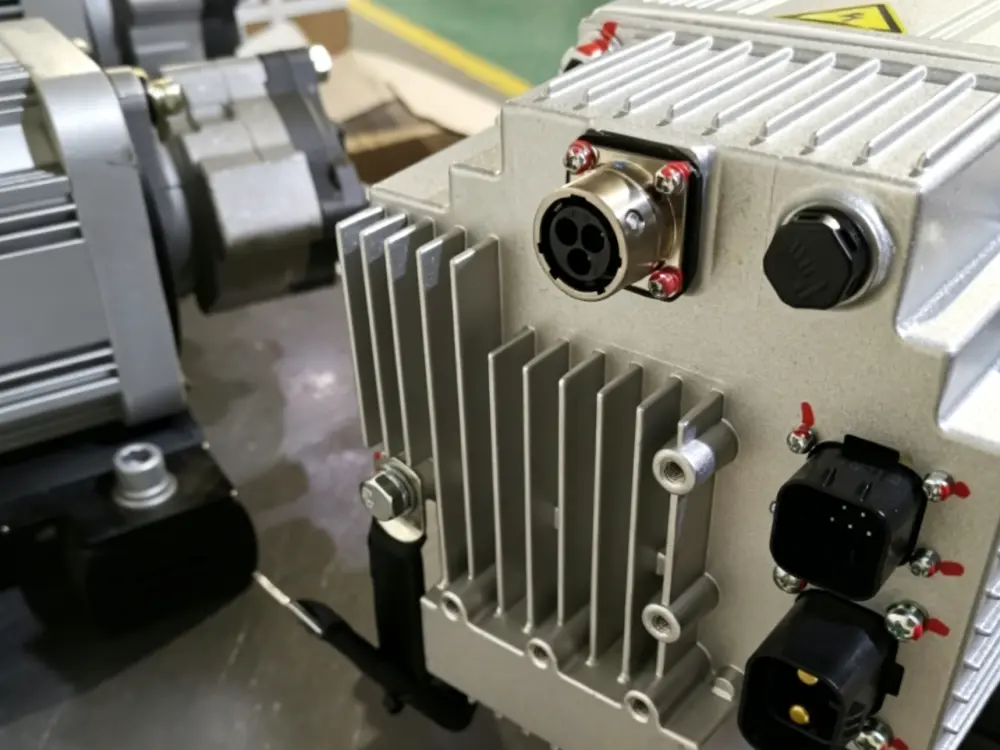
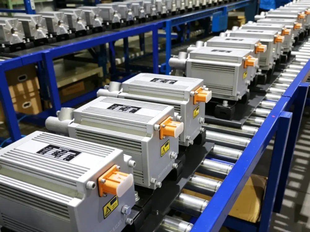
Our EHPS design uses a PMSM motor, vane pump, damping elements and an integrated rear-mounted controller. The system is designed to provide the hydraulic steering assistance required by commercial vehicle platforms while allowing pump operation to be controlled electronically.
Dual-Winding Motor Architecture
One of the available configurations uses a dual-winding PMSM architecture, with independent HV and LV windings on the same rotor and shaft. The windings are electrically isolated within the stator.
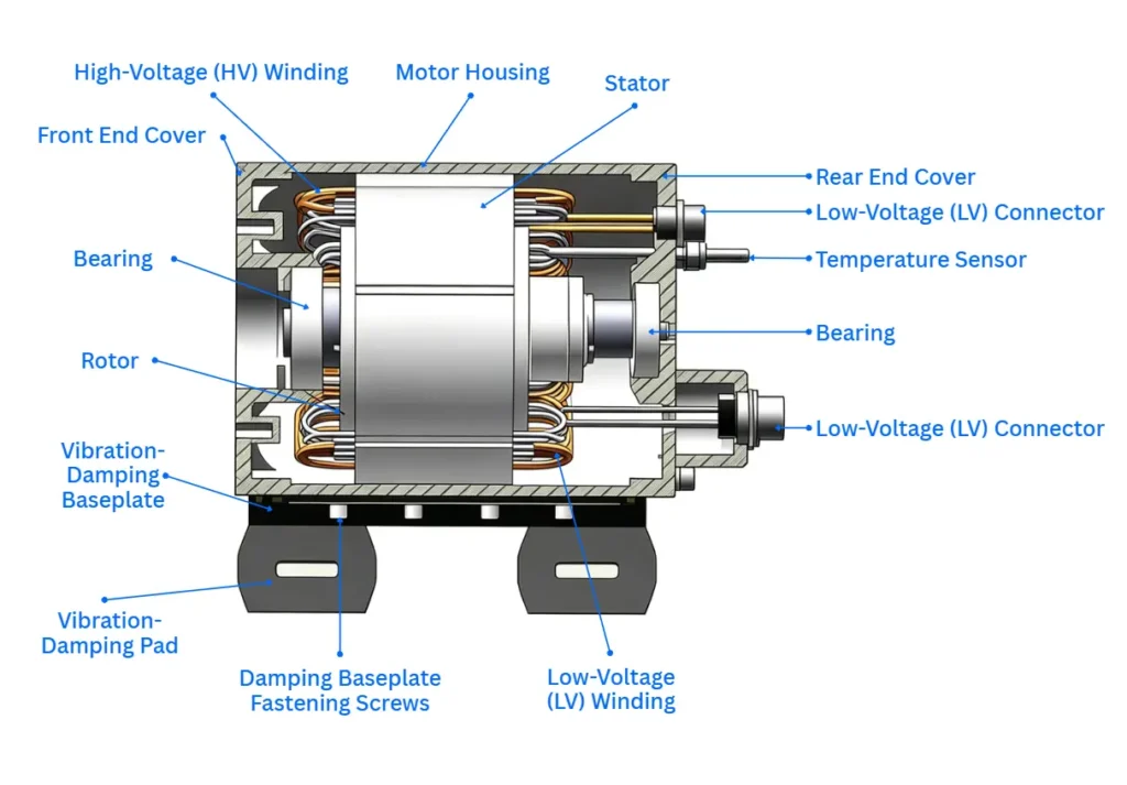
This configuration provides an additional level of operational redundancy. If the HV side becomes unavailable, the LV winding can continue to operate the pump, subject to the system’s operating conditions and control strategy.
A magnetic encoder is integrated into the motor-control system to provide rotor position information for motor control.
Looking for a EHPS or EPS solution for an electric bus, heavy commercial vehicle or off-highway platform? You can contact our team at contact@jenwyntech.com or complete the form below.