
Lithium-ion batteries are widely used in electric buses because of their high operating voltage, high energy density, long cycle life, and low self-discharge rate. However, battery charging and discharging performance is affected by temperature. Operation at excessively high or low temperatures can reduce battery performance and accelerate degradation, while improper charging or discharging under extreme conditions may also create safety risks.
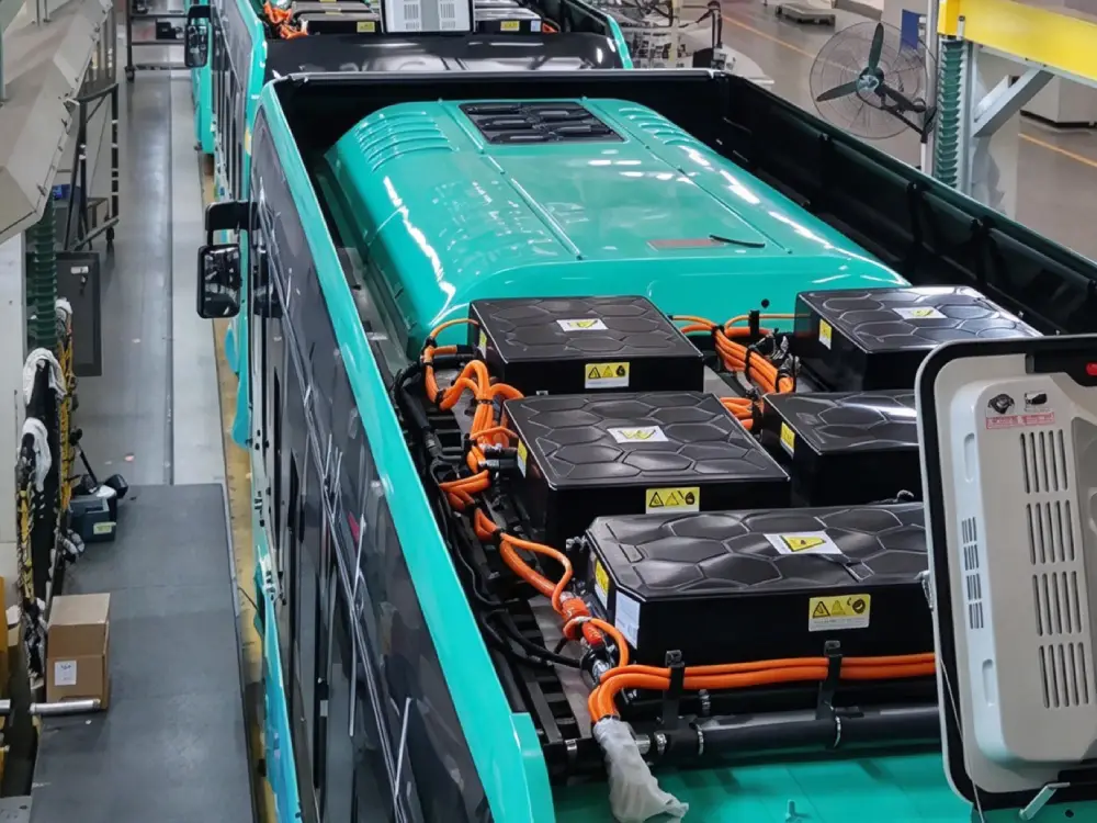
For electric buses operating in both hot and cold climates, an effective battery thermal management system (BTMS) is therefore an important part of the vehicle’s battery system. Its primary purpose is to manage battery temperature through cooling and heating, keeping the battery within an appropriate operating range under different operating and charging conditions.
A battery thermal management system typically includes a cooling circuit, heating circuit, electrical interfaces, and a control system connected with the battery management system (BMS).
1. Battery Cooling and Heating System Design
1.1 Cooling Methods
Air cooling and liquid cooling are two commonly used approaches for battery thermal management.
Air cooling relies on airflow to remove heat from the battery through convection. For battery enclosures that require a high level of environmental protection, however, introducing airflow into the enclosure can make it more difficult to achieve the required sealing performance.
Liquid cooling uses a coolant as the heat-transfer medium. Heat generated by the battery is transferred through a cooling interface and carried away by the circulating coolant. This approach can support sealed battery enclosure designs and is widely used in electric vehicle battery systems where thermal control and environmental protection are important.
A typical liquid-cooled battery enclosure consists of:
- Battery modules
- Cooling plates
- Thermal interface material
- Battery enclosure
- Coolant inlet and outlet connections
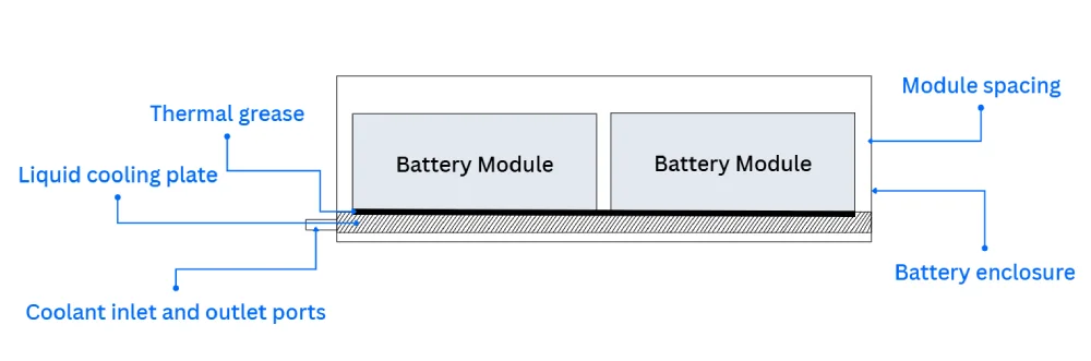
The battery modules are thermally connected to the cooling plates through a thermal interface material. Coolant flows through the cooling plates and transfers heat away from the battery modules.
1.2 Conventional Cooling Systems
A conventional liquid cooling system can use a radiator and fan to dissipate heat from the coolant. As the coolant passes through the radiator, heat is transferred to the surrounding air.
The effectiveness of this approach depends partly on ambient temperature. Under high-temperature operating conditions, the temperature difference between the coolant and surrounding air can become smaller, limiting the system’s ability to reduce coolant temperature.
For electric buses operating in hot climates or under high battery loads, a cooling system with active refrigeration can provide additional thermal control.
1.3 Refrigerant-Based Battery Cooling System
One approach is to adapt the basic operating principle of an automotive air-conditioning system for battery cooling.
Instead of directly cooling cabin air, the refrigeration circuit transfers heat from the battery coolant through a heat exchanger. A coolant pump circulates the coolant through the battery cooling plates and the heat exchanger, while the refrigeration circuit removes heat from the coolant.
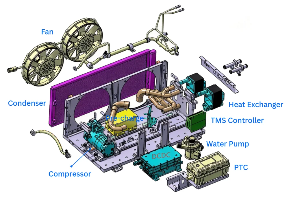
A typical system consists of:
- Electric compressor
- Condenser
- Cooling fan
- Expansion valve
- Refrigerant-to-coolant heat exchanger
- Coolant pump
- Coolant and refrigerant lines
- Controller
- Electrical harnesses
Operating Principle
During operation, the electric compressor circulates the refrigerant through the refrigeration circuit. After passing through the condenser and expansion valve, the refrigerant enters the heat exchanger at a lower temperature and absorbs heat from the battery coolant.
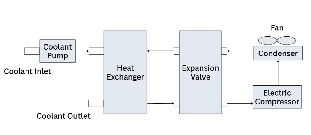
At the same time, the coolant pump circulates coolant between the battery cooling circuit and the heat exchanger. Heat generated by the battery is transferred to the coolant and then removed through the heat exchanger.
The controller can regulate the operation of the compressor, fan, and coolant pump according to temperature requirements and system operating conditions. This allows the cooling capacity to be adjusted according to the battery’s thermal load.
Integrated System Design
For electric bus applications, the cooling components can be integrated into a dedicated system enclosure. The enclosure can incorporate high-voltage and low-voltage electrical interfaces, as well as coolant inlet and outlet connections.
An integrated design can simplify installation and maintenance by reducing the number of separate components that need to be packaged within the vehicle. It can also provide a more standardized system architecture for different vehicle platforms.
1.4 Battery Heating System
Battery thermal management is not limited to cooling. At low temperatures, battery charging and discharging performance can also be restricted. A heating system can therefore be integrated into the same coolant circuit.
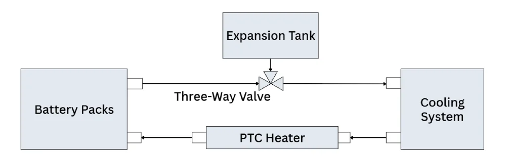
For a liquid-cooled battery, one practical approach is to install a liquid PTC heater in series with the coolant circuit.
When the PTC heater is activated, it heats the circulating coolant before the coolant enters the battery cooling plates. The heated coolant transfers thermal energy to the battery modules, gradually increasing battery temperature.
A typical automotive PTC coolant heater includes:
- Control module
- Heating element
- Coolant flow channel
- Housing
The control module generally incorporates high-voltage switching and low-voltage communication functions. It can communicate with the battery thermal management controller and control the heating element according to coolant temperature and system operating requirements.
2. Electrical Interfaces and Control Strategy
After the cooling and heating circuits are defined, the battery thermal management system also requires appropriate electrical interfaces and control logic.
The system typically requires:
- High-voltage DC power for high-voltage loads such as the electric compressor and PTC heater
- Low-voltage power for components such as the coolant pump, fan, and controller
- Communication with the BMS for temperature monitoring, operating commands, and fault information
The BMS and thermal management controller work together to determine when cooling or heating should be activated and how the system should respond to abnormal operating conditions.
2.1 Typical Thermal Management Modes
Depending on vehicle operating conditions, the battery thermal management system can support several operating modes, including:
- Charging heating
- Charging cooling
- Driving heating
- Driving cooling
- Pre-drive heating or cooling
- Fault diagnosis and protection
- Thermal protection
Charging Heating and Cooling
During charging, the BMS monitors battery temperature and determines whether heating or cooling is required.
When the battery temperature is below the defined low-temperature threshold, the heating system can be activated before or during charging to bring the battery into an appropriate temperature range.
When battery temperature rises above the defined cooling threshold, the cooling system can be activated to remove heat generated during charging.
In the system described in this design, the heating thresholds are set at approximately 5°C and 10°C, while the cooling thresholds are approximately 30°C and 26°C. These values represent the control logic of the referenced system and should be calibrated according to the battery chemistry, cell specifications, BMS strategy, and vehicle operating requirements.
Driving Heating and Cooling
During vehicle operation, the BMS continuously monitors battery temperature.
When battery temperature falls below the defined low-temperature threshold, the heating system is activated. Once the battery reaches the specified upper heating threshold, heating is stopped.
Similarly, when battery temperature exceeds the defined cooling threshold, the cooling system is activated. Cooling is stopped once the battery temperature returns below the specified lower threshold.
This type of hysteresis-based control helps prevent frequent switching between heating or cooling states.
Pre-Drive Heating and Cooling
Before the vehicle starts, battery temperature can also be considered as part of the vehicle start-up strategy.
For low battery temperatures, the heating system can operate before vehicle operation to bring the battery to the required temperature range.
If battery temperature is high, the vehicle can enter the ready state while cooling is activated once the vehicle starts, depending on the vehicle control strategy.
The exact thresholds and operating sequence should be defined according to the battery manufacturer’s requirements and the vehicle’s BMS and VCU control logic.
2.2 Fault Diagnosis and Protection
A battery thermal management system should continuously monitor the operating status of its key components and communicate abnormal conditions to the BMS.
Potential monitored conditions include:
- High or low supply voltage
- Abnormal refrigerant pressure
- Compressor overload or over-temperature
- Compressor communication faults
- Coolant pump faults
- Fan faults
- PTC heater faults
- Communication faults
- Abnormal coolant outlet temperature
When a critical fault is detected, the thermal management controller can stop the relevant subsystem and transmit a fault signal to the BMS. Depending on the fault type and vehicle control strategy, the BMS can then disconnect the relevant high-voltage supply.
This coordinated approach allows the battery thermal management system to respond to component faults while maintaining appropriate protection of the battery system.
2.3 Thermal Event Protection
Battery thermal events require a different control strategy from normal temperature regulation.
If the BMS detects an abnormal and rapid increase in battery temperature, it can issue a battery fault warning and command the thermal management system to enter a high-cooling-capacity mode.
Under the control strategy described in the referenced system, the compressor, coolant pump, and cooling fan can operate at high output to maximize heat removal.
If the battery temperature continues to rise and reaches a defined protection threshold, the control strategy can change again. The high-voltage supply to the refrigeration system may be disconnected while the coolant pump remains active, allowing coolant circulation to continue.
This approach is intended to maximize heat transfer from the battery even after the refrigeration compressor has been stopped. It may help slow the temperature rise and provide additional time for the vehicle’s safety systems to respond.
Thermal-event protection must be designed as part of the overall battery safety architecture. The actual control thresholds, response sequence, and safety functions should be determined based on the battery system design, BMS strategy, applicable safety requirements, and vehicle-level validation.
3. Conclusion
Battery temperature has a direct influence on the operating performance and charging capability of an electric bus battery system. A suitable battery thermal management system therefore needs to address both high-temperature cooling and low-temperature heating.
For liquid-cooled battery systems, active refrigeration can provide controlled coolant cooling under high thermal loads, while a liquid PTC heater can provide controlled heating at low temperatures. Integrating these functions with the BMS enables the system to manage battery temperature across charging, driving, and pre-drive conditions while also providing fault monitoring and protection.
For electric bus platforms, the thermal management system should ultimately be matched to the battery chemistry, battery pack design, vehicle operating conditions, climate, and overall electrical architecture. Proper integration of the cooling circuit, heating circuit, electrical interfaces, and control strategy is essential for reliable battery operation across different environmental conditions.
Jewnyn Tech BTMS Solutions for Commercial EVs
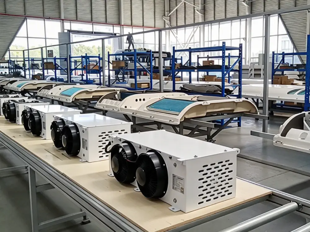
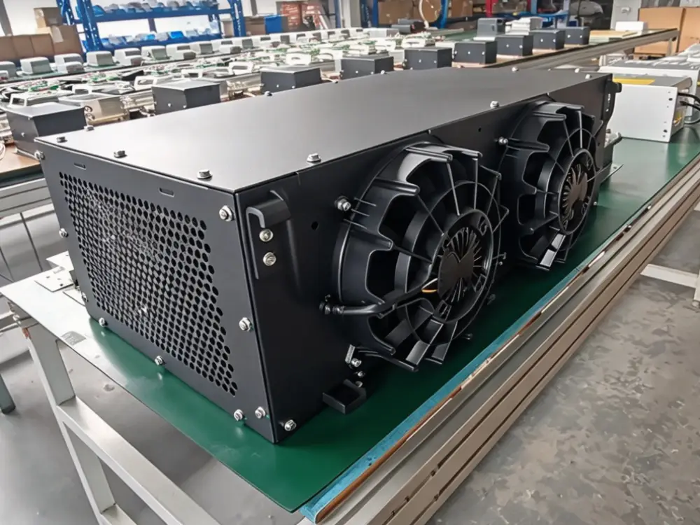
Jenwyn Tech provides liquid-cooled BTMS solutions for electric buses, trucks, logistics vehicles, and specialty EVs, with 2–12 kW cooling capacity, roof-mounted and skirt-mounted configurations, and optional heating functions. CAN-based control enables communication with the vehicle BMS for coordinated battery temperature management.

Explore our Battery Thermal Management Systems (BTMS) →
For project-specific requirements, contact our team to discuss your battery voltage, capacity, cooling requirements, installation space, and vehicle application. You can contact our team at contact@jenwyntech.com or complete the form below.