
Selecting the right electric bus motor is not an isolated decision; it is a system-level optimization exercise. The performance of the traction motor is fundamentally constrained by the capabilities of its controller (inverter), and the choice of mechanical architecture dictates the duty cycle efficiency.
For commercial vehicle OEMs and system integrators, designing the optimal electric bus motor powertrain involves navigating critical trade-offs between inverter current capacity, Back-EMF limits, vehicle voltage platform, and transmission architecture.
This technical guide analyzes these trade-offs to help you define the right electric bus motor configuration for your vehicle platform.
1. Inverter Boundaries: Setting the Electric Bus Motor Limits
In a commercial EV powertrain, the motor controller (inverter) defines the operational envelope of the traction motor. Downsizing the inverter directly lowers system costs, but it also caps the phase current available to the motor.
Standard IGBT Module Ratings
Most commercial vehicle inverters utilize 1200V IGBT power modules. At a standard nominal DC bus voltage of 540V, common IGBT ratings yield the following maximum phase current and output power limits:
| IGBT Module Rating | Max Output Phase Current (Irms) | Max Output Power (@ 540V DC) |
|---|---|---|
| 1200V / 450A | 290 A | 120 kW |
| 1200V / 600A | 380 A | 180 kW |
1200V / 900A (450A×2) | 560 A | 280 kW |
1200V / 1200A (600A×2) | 700 A | 350 kW |
The Impact of Voltage and Back EMF
- Voltage Scaling: When pairing a given electric bus motor and inverter, peak torque remains constant across different battery voltages (as torque is primarily a function of current). However, peak power scales proportionally with the operating DC voltage (
P=Vbus×IpeakP=Vbus×Ipeak). - Back-EMF Constraints: Back-electromotive force (BEMF) limits the maximum speed of the electric bus motor. A motor designed for high torque output per unit of current (high torque density) inherently has a higher BEMF coefficient, which limits its achievable top speed.
For a fixed controller current rating, this creates a direct inverse relationship between peak torque and maximum speed:
| Peak Motor Torque | Maximum Motor Speed |
|---|---|
| 350 N.m | 10000 rpm |
| 500 N.m | 7500 rpm |
| 750 N.m | 4500 rpm |
| 1000 N.m | 3200 rpm |
| Peak Motor Torque | Maximum Motor Speed |
|---|---|
| 1000 N.m | 4500 rpm |
| 1250 N.m | 3600 rpm |
| 1700 N.m | 3000 rpm |
| 2100 N.m | 2500 rpm |
| Peak Motor Torque | Maximum Motor Speed |
|---|---|
| 900 N.m | 7500 rpm |
| 1500 N.m | 4500 rpm |
| 2000 N.m | 3200 rpm |
| 2500 N.m | 2800 rpm |
| Peak Motor Torque | Maximum Motor Speed |
|---|---|
| 2000 N.m | 4200 rpm |
| 2500 N.m | 3600 rpm |
| 2800 N.m | 3000 rpm |
| 3200 N.m | 2600 rpm |
2. Architecture Selection: Direct Drive vs. Transmission-Integrated
When using the same inverter class, a motor’s boundary envelope remains roughly constant:
Peak Torque × Rotational Speed ≈ ConstantPeak Power ≈ ConstantA gearbox multiplies output torque while reducing output speed. Consequently, integrating a transmission allows a significantly smaller, higher-speed motor to deliver the same wheel torque as a large, low-speed direct-drive motor, allowing the OEM to downsize the required inverter.
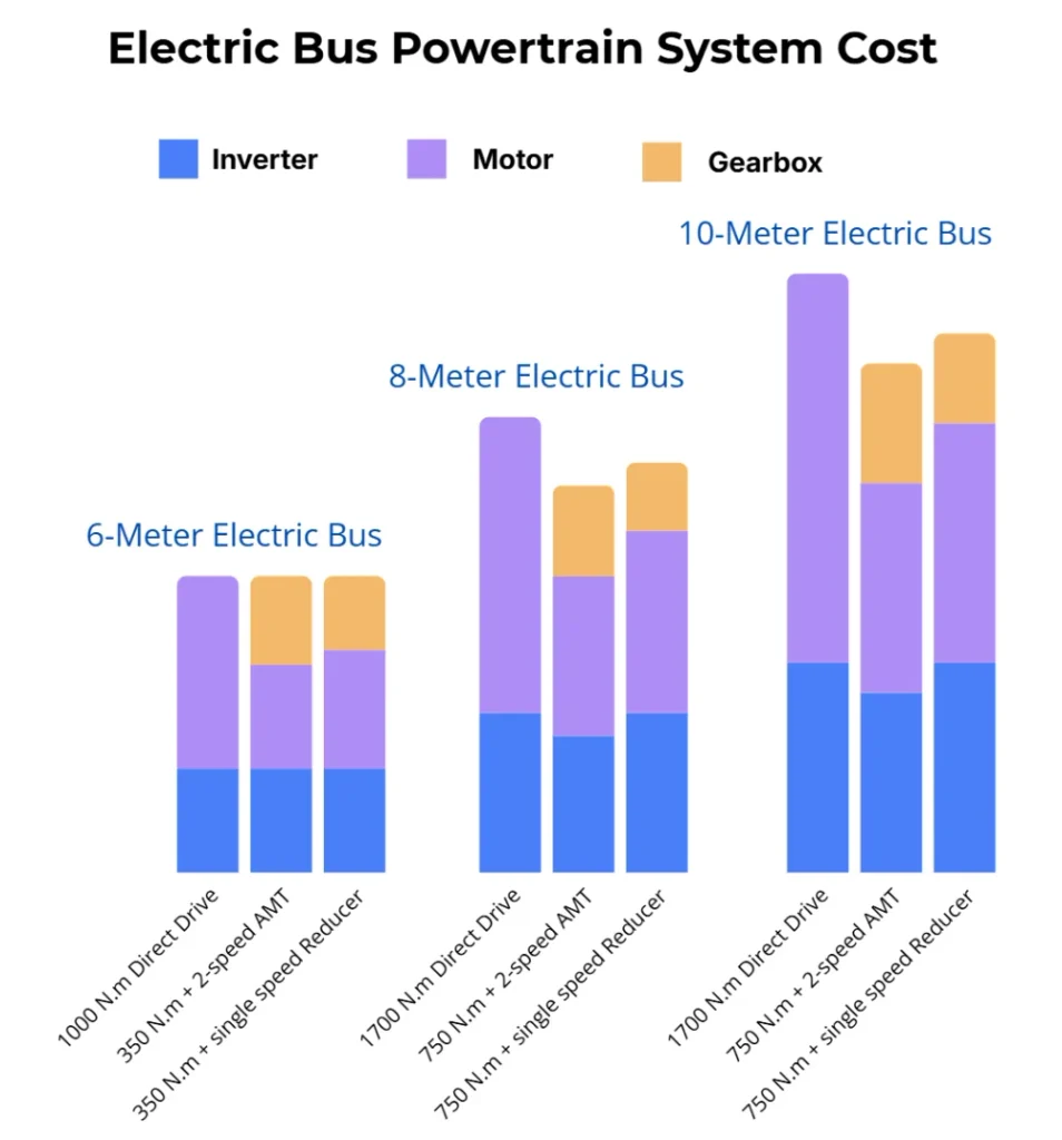
Electric City Bus (Transit) Sizing Matrix
Transmission configuration utilizes a 1st gear ratio of approximately 2.7:1.
| Bus Length | Max Power Demand | Direct Drive: Max Motor Torque | Direct Drive: Max Motor Speed | Direct Drive: Inverter | Transmission:Max Motor Torque | Transmission:Max Motor Speed | Transmission: Inverter |
|---|---|---|---|---|---|---|---|
| 6-meter Bus | 90 kW | 1,000 Nm | 3,200 rpm | 450A | 350 Nm | 3,200 rpm | 450A |
| 8-meter Bus | 120 kW | 1,700 Nm | 3,000 rpm | 600A | 650 Nm | 3,000 rpm | 450A |
| 10-meter Bus | 140 kW | 2,800 Nm | 2,600 rpm | 900A | 900 Nm | 2,600 rpm | 600A |
Electric Coach / Intercity Bus Sizing Matrix
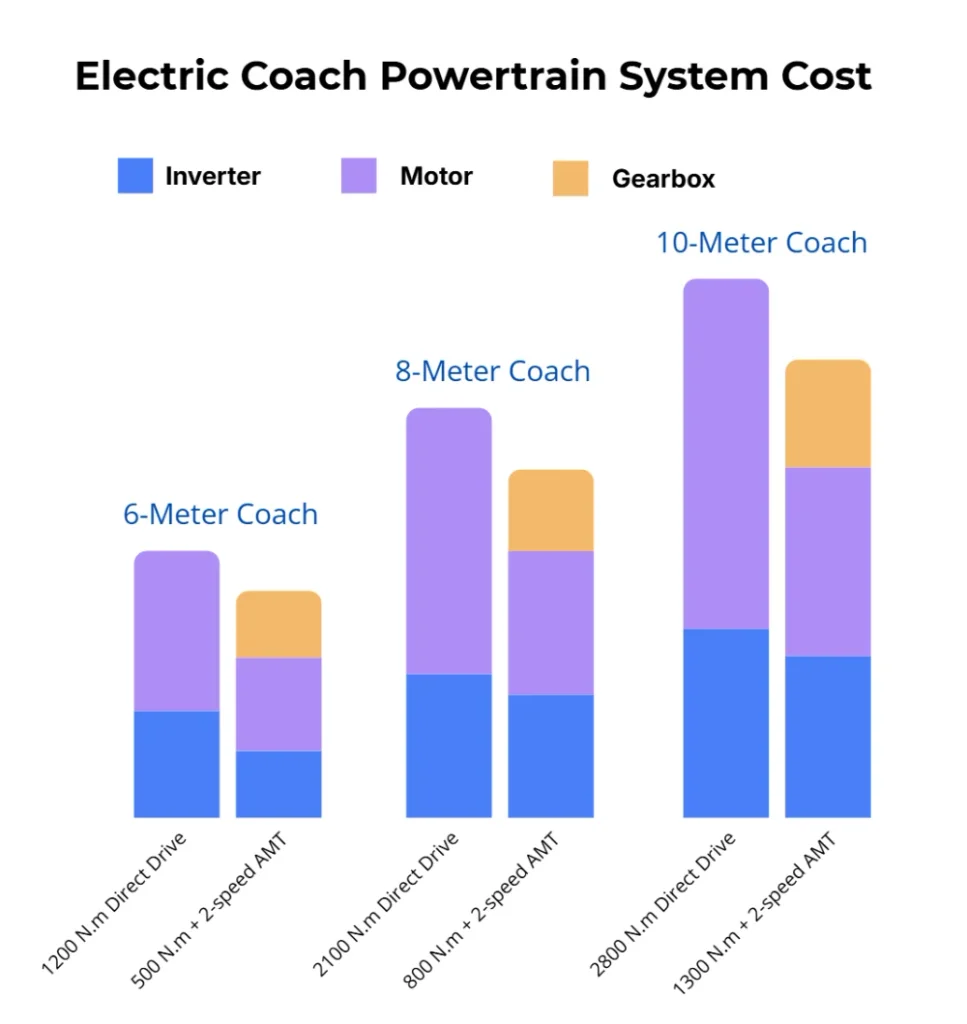
Transmission configuration utilizes a 1st gear ratio of approximately 2.7:1.
| Coach Length | Max Power Demand | Direct Drive: Max Motor Torque | Direct Drive: Max Motor Speed | Direct Drive: Inverter | Transmission:Max Motor Torque | Transmission:Max Motor Speed | Inverter |
|---|---|---|---|---|---|---|---|
| 6-meter Coach | 110 kW | 1,200 Nm | 4,500 rpm | 600A | 350 Nm | 4,500 rpm | 450A |
| 8-meter Coach | 150 kW | 2,100 Nm | 3,500 rpm | 900A | 800 Nm | 3,500 rpm | 600A |
| 10-meter Coach | 180 kW | 2,800 Nm | 3,000 rpm | 1200A | 1,100 Nm | 3,000 rpm | 600A |
Electric Bus & Coach Powertrain System Cost Comparison
| Vehicle Type | Direct Drive | Transmission | Single-Speed Reducer |
|---|---|---|---|
| 6 M bus | ★★★ | ★★ | ★★ |
| 8+ M bus | ★★ | ★★★ | ★★ |
| 6+ M coach | ★★ | ★★★ | ★★ |
3. Operating Efficiency Across Drive Cycles
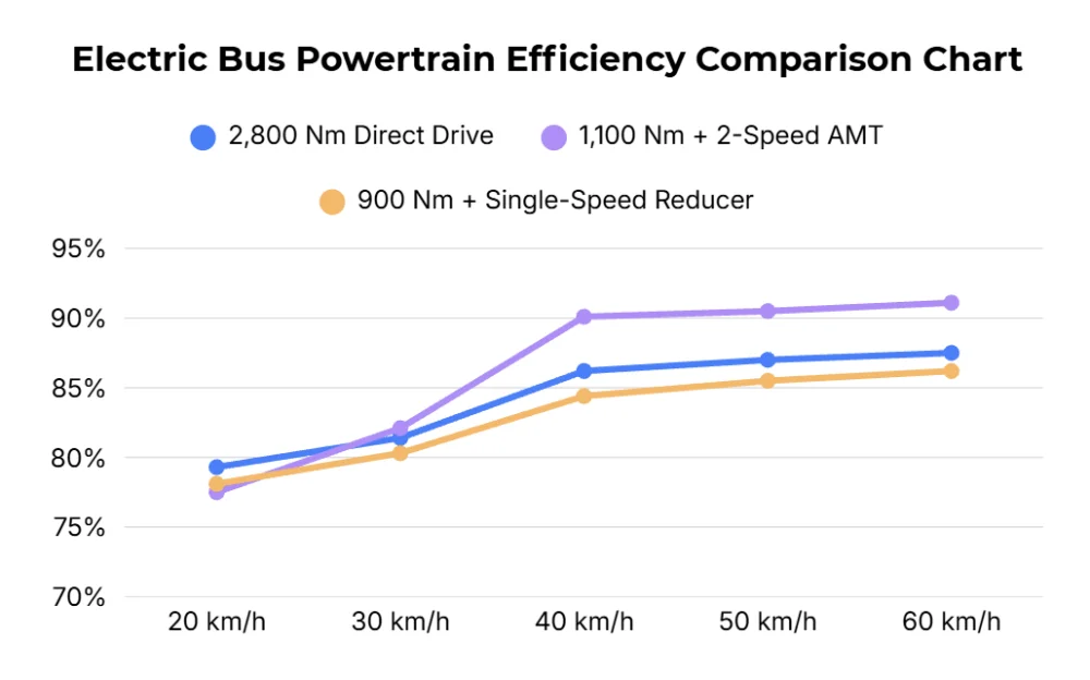
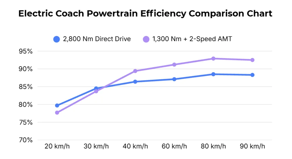
While direct-drive layouts eliminate transmission mechanical losses, multi-speed architectures allow the traction motor to operate in its peak efficiency island across a wider vehicle speed range.
Case 1: 10–12 Meter Electric City Bus Powertrain Comparison
| Parameter | 2,800 Nm Direct Drive | 1,100 Nm Motor + 2-Speed AMT | 900 Nm Motor + Single-Speed Reducer |
|---|---|---|---|
| Motor Peak Torque | 2,800 Nm | 1,100 Nm | 900 Nm |
| Motor Peak Power | 200 kW | 160 kW | 160 kW |
| Motor Max Speed | 2,500 rpm | 4,500 rpm | 7,500 rpm |
| Transmission Ratio | / | 2.6 / 1.0 | 3.04 |
| Max System Output Torque | 2,800 Nm | 2,860 Nm | 2,736 Nm |
Constant-Speed Efficiency (10–12m Electric City Bus)
| Vehicle Speed | 2,800 Nm Direct Drive | 1,100 Nm + 2-Speed AMT | 900 Nm Motor + Single-Speed Reducer |
|---|---|---|---|
| 20 km/h | 79.3% | 77.5% | 78.1% |
| 30 km/h | 81.4% | 82.1% | 80.3% |
| 40 km/h | 86.2% | 90.1% | 84.4% |
| 50 km/h | 87.0% | 90.5% | 85.5% |
| 60 km/h | 87.5% | 91.1% | 86.2% |
Case 2: 10-Meter Intercity Coach Powertrain Comparison
| Parameter | 2,800 Nm Direct Drive | 1,300 Nm Motor + 2-Speed AMT |
|---|---|---|
| Motor Peak Torque | 2,800 Nm | 1,300 Nm |
| Motor Peak Power | 250 kW | 185 kW |
| Motor Max Speed | 3,000 rpm | 3,500 rpm |
| Transmission Ratio | / | 2.6 / 1.0 |
| Max System Output Torque | 2,800 Nm | 3,380 Nm |
Constant-Speed Efficiency (10m Coach)
| Vehicle Speed | 2,800 Nm Direct Drive | 1,300 Nm + 2-Speed AMT |
|---|---|---|
| 20 km/h | 79.7% | 77.7% |
| 30 km/h | 84.5% | 83.7% |
| 40 km/h | 86.4% | 89.4% |
| 60 km/h | 87.1% | 91.2% |
| 80 km/h | 88.5% | 92.9% |
| 90 km/h | 88.3% | 92.5% |
Electric Bus & Coach Powertrain System Efficiency Summary by Application
| Architecture | City Bus: Low-Speed Steady | City Bus: Mid/High-Speed Steady | City Bus: Dynamic Cycle | Coach: Low-Speed Steady | Coach: Mid/High-Speed Steady | Coach: Dynamic Cycle |
|---|---|---|---|---|---|---|
| Direct Drive | ★★★ | ★★ | ★★ | ★★★ | ★★ | ★★ |
| Multi-Speed AMT | ★★ | ★★★ | ★★★ | ★★ | ★★★ | ★★★ |
| Single-Speed Reducer | ★★ | ★ | ★ | — | — | — |
Direct drive provides high efficiency during low-speed continuous cruising due to zero gearbox friction. However, across dynamic duty cycles and sustained medium-to-high speeds, multi-speed AMT delivers higher net system efficiency by keeping the electric motor in its optimal torque-speed map.
4. System Mass and Cost Analysis
Mass Reduction via Torque De-multiplication
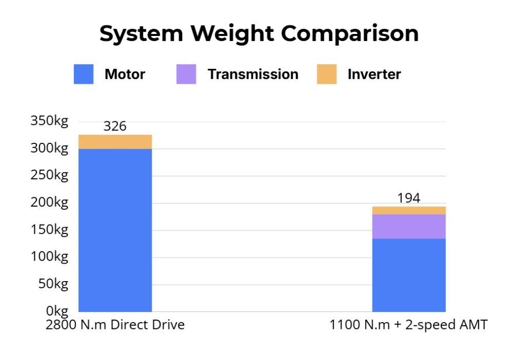
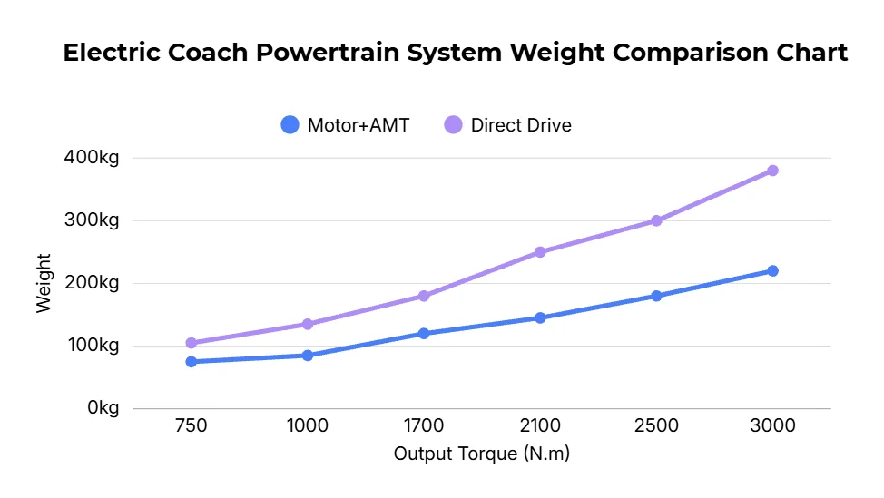
Using a mechanical transmission lowers the motor’s required torque output, directly reducing the active electromagnetic material (copper and iron lamination mass) required in the motor. As target wheel torque demands increase, the mass reduction achieved by an AMT architecture becomes more pronounced.
Cost Evaluation
System-level costs are optimized when minimizing the combined expense of the inverter, motor, and transmission:
- For smaller commercial vehicles (such as 6m city buses), the simplicity and lower component count of direct drive or single reduction often yields competitive costs.
- For vehicles exceeding 8 meters in length, the savings from downsizing the inverter module (e.g., specifying a 450A or 600A controller instead of 900A or 1200A) and reducing motor raw material mass outweigh the cost of adding a compact 2-speed transmission.
| Vehicle Application | Platform Size | Direct Drive | Multi-Speed Transmission | Single-Speed Reducer |
|---|---|---|---|---|
| City Bus | 6m | Preferred | Viable | Viable |
| City Bus | ≥8m | Viable | Preferred | Viable |
| Highway Coach | ≥6m | Viable | Preferred | Viable |
5. Engineering Implementation: Modular Powertrain Architecture and Driveline Reliability
To address the demanding duty cycles, structural packaging limits, and service life requirements of commercial passenger transit, Jenwyn Tech employs a standardized modular powertrain architecture. This platform strategy minimizes vehicle integration complexity for OEMs while maximizing mechanical reliability over multi-year fleet operations.
Modular Platform Strategy (4 m to 12 m Coverage)
A modular configuration allows vehicle manufacturers to cover city buses and coaches ranging from 4 meters to 12 meters using three transmission models matched across six motor variants:
- Fixed Lamination Diameters with Scalable Stack Length: The traction motors share a standardized stator and rotor lamination outer diameter. Torque scaling is achieved solely by varying the axial iron core stack length and motor housing, eliminating the need to redesign mechanical mounting interfaces.
- Shared Structural Architecture: Matching variants utilize standardized front and rear end-caps, bellhousings, and chassis mounting interfaces.
- Component Commonality: This approach drastically reduces proprietary tooling costs, accelerates CAD packaging and vehicle chassis integration timelines, and streamlines spare parts management for fleet operators.
Transmission Engineering: Eliminating Mechanical Wear Points
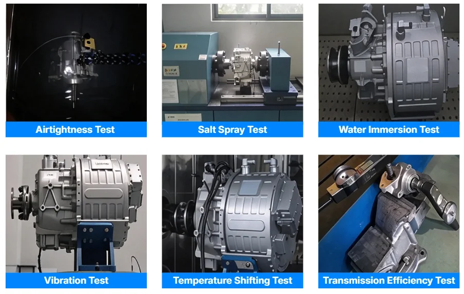
High-utilization transit operations generate tens of thousands of shift events annually. Reliability is improved by removing high-wear frictional components:
- Synchronizer-Less Dog-Clutch Architecture: The multi-speed transmission eliminates traditional friction synchronizer rings—one of the most common failure points in commercial vehicle transmissions—replacing them with robust mechanical dog clutches.
- Active Inverter Speed Synchronization: Mechanical friction synchronization is replaced by precise motor speed and torque matching governed by the inverter. During shifting, the motor rapidly matches input shaft speed to target gear speed under near-zero torque conditions, ensuring fast, smooth gear transitions with minimal driveline shock.
Our offerings:
| Model | Rated / Peak Power | Rated / Peak Torque | Transmission | Gear Ratio |
|---|---|---|---|---|
| EDU75-SA01 | 75 kW / 120 kW | 350 N.m / 850 N.m | 2-speed AMT | 2.741, 1 |
| EDU110-SA01 | 110 kW / 220 kW | 500 N.m / 1100 N.m | 2-speed AMT | 2.741, 1 |
| EDU120-SA01 | 120 kW / 185 kW | 750 N.m / 1300 N.m | 2-speed AMT | 2.741, 1 |
Flexible Supply Models: From Powertrain Kits to Complete Electric Buses
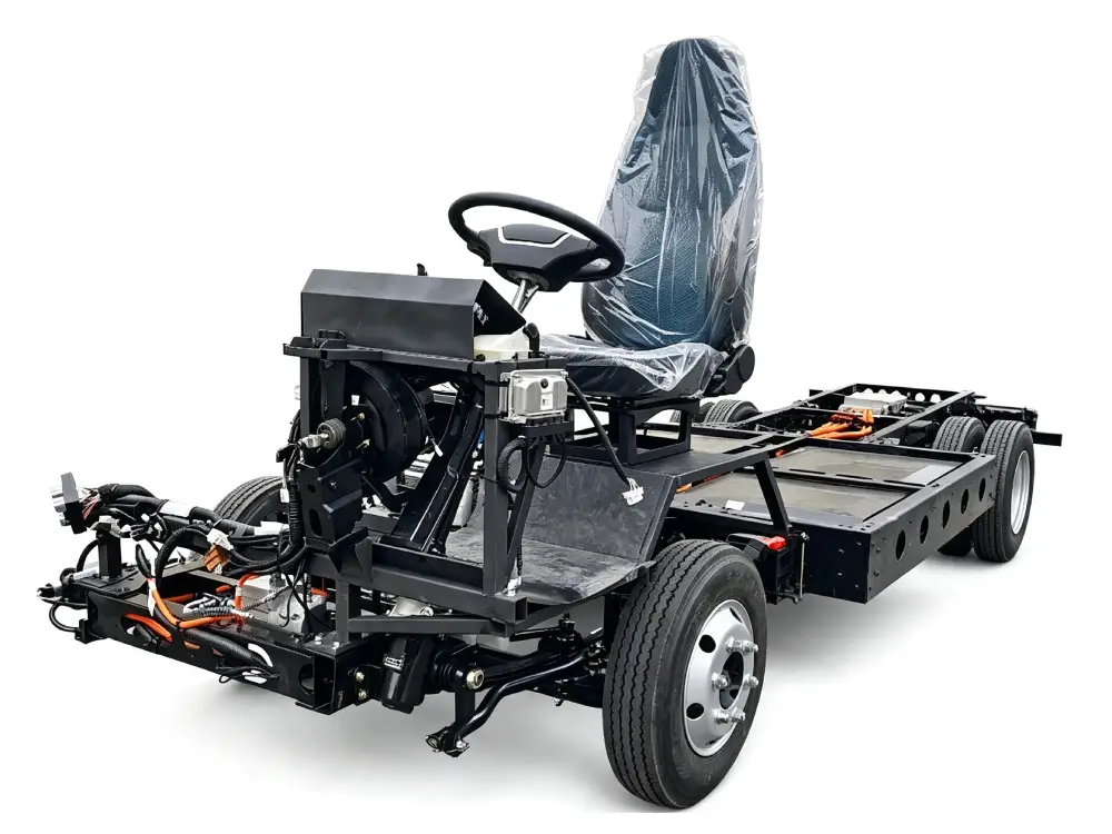
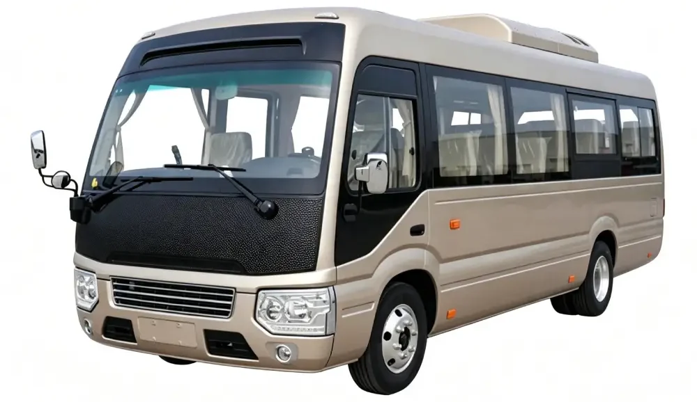
Jenwyn Tech supports electric bus or coach projects at multiple integration levels. Whether you are a vehicle manufacturer sourcing a modular electric powertrain, a bus bodybuilder requiring a validated rolling chassis, or an operator seeking turnkey electric vehicles, our team can supply the configuration that matches your project requirements.
Choose Your Integration Level
- 1. Integrated Powertrain Systems
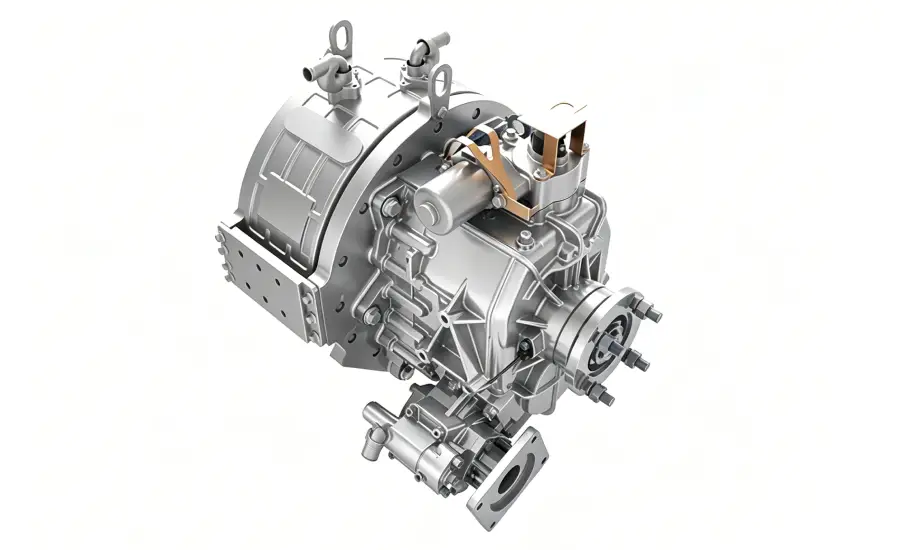
Modular traction motor, 2-speed synchronizer-less transmission, and matched inverter ready for integration into your proprietary vehicle chassis. - 2. Electric Bus Chassis (Rolling Chassis Platforms)
Electrified chassis platforms covering 6 m to 12 m passenger transit applications. Pre-integrated with electric powertrains, steering, pneumatic braking, and high-voltage distribution—allowing regional bodybuilders and coachbuilders to mount customized bus bodies efficiently. - 3. Complete Electric Buses
Production-ready urban transit buses and commercial shuttles built for fleet deployment, configured to meet your target passenger capacity, daily route mileage, and local operational requirements.
Discuss Your Project With Our Team
To help us evaluate the right architecture and provide relevant technical documentation, share your basic project scope with us:
- Required supply scope (Powertrain Kit / Electric Chassis / Complete Bus)
- Vehicle class, chassis length, and target GVW
- Operating conditions (daily mileage, route profile, target gradeability, and top speed)
- Battery capacity or platform voltage requirements
👉You can contact our team at contact@jenwyntech.com or complete the form below.