
As electric vehicle power electronics continue to evolve, system integration has become an important direction in on-board charger development. Combining the on-board charger (OBC) with a high-voltage DC/DC converter can reduce packaging volume, wiring, connectors, and overall system complexity while improving integration with the vehicle’s electrical architecture.
At the same time, higher charging power, wider battery voltage ranges, bidirectional energy flow, and the adoption of silicon carbide (SiC) devices are driving changes in OBC power topologies and control strategies.
This article reviews commonly used EV OBC architectures, with a focus on integrated OBC + DC/DC solutions, including 6.6 kW and 11 kW configurations. It also examines key electrical and control parameters, efficiency and power factor requirements, semiconductor selection, thermal management, and the main engineering challenges facing next-generation OBC systems.
1. OBC Architecture and Basic Operating Principle
An on-board charger converts AC power from the charging infrastructure into DC power suitable for the vehicle’s high-voltage battery. A typical OBC uses a two-stage power conversion architecture: AC input → PFC → DC link → Isolated DC/DC → HV battery
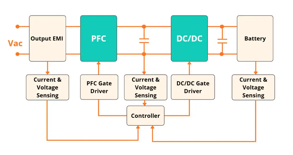
The front-end power factor correction (PFC) stage regulates the AC input current and maintains a stable DC-link voltage. The downstream isolated DC/DC stage converts the DC-link voltage to the voltage and current required by the battery while providing the required electrical isolation.
In an integrated OBC + DC/DC unit, the OBC handles AC-to-HV DC conversion, while the integrated DC/DC converter converts high-voltage battery power to the vehicle’s 12 V or 24 V low-voltage electrical system.
This allows one integrated unit to handle both battery charging and low-voltage power conversion. The increasing use of integrated architectures reflects a broader trend toward consolidating high-voltage power electronics within the EV electrical system.
2. Integrated OBC + DC/DC Architectures
6.6 kW OBC + DC/DC
A 6.6 kW on-board charger combined with a DC/DC converter is a practical configuration for EV platforms that do not require higher-power three-phase AC charging. A representative architecture consists of: AC input → PFC → Bidirectional LLC → HV battery with an additional low-voltage DC/DC stage for the vehicle’s 12 V or 24 V electrical system.
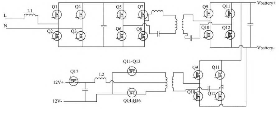
A representative design can use SiC MOSFETs selectively in the PFC stage while using silicon MOSFETs in other stages. This approach allows semiconductor selection to be optimized according to the requirements of each power stage rather than using SiC devices throughout the system.
Digital controllers can be used for the PFC and DC/DC stages, with an automotive-grade MCU supporting vehicle communication and system coordination.
The main advantages of an integrated 6.6 kW on-board charger + DC/DC architecture include:
- Reduced packaging volume
- Fewer high-voltage connections
- Shared thermal management
- Simplified mechanical integration
- Reduced system-level cost
For compact EV and light commercial vehicle platforms, this configuration provides a practical balance between charging power, efficiency, packaging, and cost.other compact EV platforms, a 6.6 kW-class OBC + DC/DC can provide a practical balance between charging capability, efficiency, packaging, and cost.
11 kW Bidirectional OBC + DC/DC
An 11 kW on-baord charger + DC/DC architecture can support both single-phase and three-phase AC input, depending on the system design. A representative configuration can provide:
- Up to approximately 6.6 kW with single-phase input
- Up to approximately 11 kW with three-phase input
- Bidirectional power conversion
- DC/DC conversion for the low-voltage system
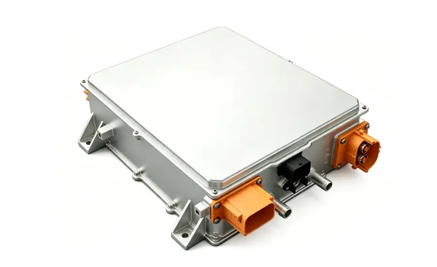
Bidirectional operation allows energy to flow in both directions: AC grid ↔ On-Board Charger ↔ HV battery
This provides the hardware basis for applications such as vehicle-to-load (V2L), vehicle-to-home (V2H), and vehicle-to-grid (V2G), when supported by the complete vehicle, charging, communication, and regulatory systems.
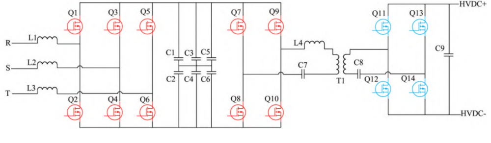
A full-SiC power stage can be used to reduce switching losses. Separate digital controllers for the PFC and LLC stages can adjust the DC-link voltage according to the battery operating point, helping optimize conversion efficiency.
Typical protection functions include:
- Input overvoltage and undervoltage
- Input overcurrent
- DC-link overvoltage
- Output overvoltage and undervoltage
- Output overcurrent
- Short-circuit protection
- Overtemperature protection
CAN communication can be used for vehicle-level communication and coordination with other control systems.
3. Key OBC Design Parameters
3.1 Input and Output Voltage
The OBC input voltage should be designed according to the target charging infrastructure and market. Typical requirements include:
- 110–240 V AC single-phase
- 380 V AC three-phase
For a wider single-phase input range, approximately 85–265 V AC may be considered.
The on-board charger output voltage needs to match the operating range of the vehicle’s traction battery. Depending on the battery architecture, a typical range may be approximately 200–800 V DC.
The output current should be adjustable according to the battery charging requirements. For example, at a 320 V output, the charging current may reach approximately 20–30 A, depending on the OBC power rating and system design.
For bidirectional OBCs, the power stage must also support reverse power flow and the required AC output during discharge or V2X operation.
3.2 Power Rating
Common OBC power levels include:
| OBC power | Typical application |
|---|---|
| 3.3 kW | Smaller EV and PHEV platforms |
| 6.6–7 kW | Passenger vehicles and light commercial vehicles |
| 11 kW | Higher-power three-phase AC charging |
| 22 kW | High-power three-phase AC charging |
Higher charging power improves charging capability but also increases thermal load, component stress, packaging requirements, and cooling requirements. OBC power should therefore be selected according to the vehicle’s actual charging requirements and available installation space.
3.3 Efficiency and Power Factor
On-board charger efficiency is an important design parameter because conversion losses directly increase thermal load. For high-efficiency on-board charger designs, an overall efficiency target of 95% or higher can be considered. LLC resonant conversion, SiC power devices, and soft-switching techniques such as zero-voltage switching (ZVS) can help reduce switching losses and improve efficiency.
For the AC input, typical design targets include:
- Power factor (PF) ≥ 0.99
- Total harmonic distortion (THD) < 5%
Digital PFC control can regulate the input current and improve PFC performance across different operating conditions, including light-load operation.
3.4 Digital Control
OBC control systems typically use digital control algorithms for power conversion and system regulation. Typical functions include:
- Voltage and current closed-loop control
- PFC control
- DC/DC regulation
- Protection
- CAN communication
- Coordination between power stages
Depending on the architecture, separate digital controllers can be used for the PFC and DC/DC stages, with communication between the control units. Digital control enables dynamic regulation of voltage and current under changing operating conditions while supporting vehicle communication and protection functions.
3.5 Semiconductor Voltage and Temperature Ratings
Power semiconductor devices need to match the voltage, temperature, and switching requirements of the OBC. For 800 V-class battery platforms, 1200 V SiC MOSFETs can be considered for high-voltage switching stages. Device selection should take into account:
- Voltage rating
- Temperature rating
- Switching losses
- Conduction losses
- Gate-drive requirements
- Thermal performance
Magnetic components also require suitable materials and structures. Low-loss ferrite materials and optimized transformer designs can help reduce high-frequency losses and improve thermal performance.
4. SiC and High-Frequency OBC Design
SiC is an important technology direction for higher-performance OBCs.
Compared with conventional silicon devices, SiC MOSFETs can provide lower switching losses and support higher switching frequencies. This can help reduce the size of magnetic components and increase power density.
However, higher switching frequency also increases design challenges, particularly in:
- Magnetic core losses
- Winding losses
- Parasitic capacitance
- Switching transients
- Gate-drive losses
- EMI
- Thermal management
Therefore, switching frequency should be optimized together with efficiency, power density, thermal performance, EMI, and cost.
As frequency increases, the design of high-frequency transformers and inductors becomes increasingly important.
5. Thermal Management and Protection
As OBC power density increases, thermal management becomes an important design constraint.
Major heat sources include:
- Power semiconductor losses
- Transformer losses
- Inductor losses
- Capacitor losses
- Gate-drive losses
Air cooling can be used for lower-power systems, while liquid cooling is increasingly relevant for higher-power or highly integrated OBC platforms.
Liquid-cooled designs need to consider:
- Cooling-channel design
- Thermal interface performance
- Coolant compatibility
- Sealing
- Corrosion
- Pressure management
- Long-term reliability
The OBC also requires appropriate protection against electrical and thermal faults, including input abnormalities, DC-link overvoltage, output faults, short circuits, overtemperature, insulation faults, and communication errors.
Thermal management and protection should be considered as part of the power-stage design.
6. Charging Standards and Compatibility
OBC development for global EV platforms needs to account for differences in charging infrastructure and regional requirements. Relevant standards and charging ecosystems include:
OBC compatibility needs to be considered together with the charging inlet, EVSE, communication controller, BMS, and vehicle control system. The transition from 400 V-class to 800 V-class battery architectures also increases requirements for insulation, voltage ratings, protection, and operating-range optimization.
7. Current Technology Trends and Engineering Challenges
Current OBC development is focused on several key directions.
7.1 Higher Power Density
Increasing power while reducing enclosure volume requires optimization of semiconductors, magnetic components, cooling, PCB layout, packaging, and control.
7.2 Greater System Integration
OBC + DC/DC integration can reduce packaging volume and simplify vehicle electrical integration. Depending on the vehicle architecture, further integration such as OBC + DC/DC + PDU may also be considered.
7.3 SiC and Wide-Bandgap Semiconductors
SiC devices are increasingly used in higher-performance OBCs to reduce switching losses and support higher power density. Other wide-bandgap devices such as GaN may also be considered for selected applications.
7.4 Higher Battery Voltage
The move from 400 V-class to 800 V-class battery systems can reduce current at a given power level, while increasing requirements for insulation, semiconductor voltage ratings, protection, and thermal design.
7.5 Bidirectional Charging
Bidirectional OBCs enable applications such as V2L, V2H, and V2G. These functions require coordination between the OBC, battery, vehicle controls, EVSE, communication system, and external electrical system.
7.6 Cost and Performance Balance
Advanced semiconductors, magnetic materials, cooling systems, and integrated packaging can improve OBC performance but also affect system cost. The design therefore needs to balance efficiency, power density, reliability, functionality, and cost.
Jenwyn Tech OBC + DC/DC Solutions
OBC development is moving toward higher efficiency, higher power density, greater system integration, wider voltage ranges, and bidirectional operation. For EV OEMs and commercial vehicle developers, OBC selection should therefore consider battery voltage, charging power, cooling, communication, packaging, and low-voltage power requirements as part of the overall vehicle electrical architecture.
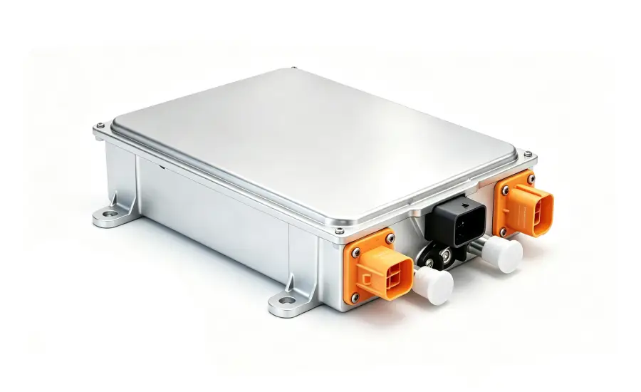
Jenwyn Tech provides OBC and integrated OBC + DC/DC solutions, with optional PDU integration for selected configurations. Our solutions cover different charging power levels and support features including bidirectional operation, flexible HV/LV power management, liquid-cooled thermal management, CAN 2.0B and UDS diagnostics, and comprehensive electrical protection. The appropriate configuration can be selected according to the vehicle’s electrical, thermal, and mechanical requirements.
Email us at contact@jenwyntech.com or fill out the inquiry form below to discuss your project requirements.